2 layers68.3 × 90 mm
ModuleController old
dennis9819/split-flap-controller
Sourcecode and Schematics for the controller of my split-flap display
25 partsAGPL-3.0
 dennis9819/split-flap-controller
Sourcecode and Schematics for the controller of my split-flap display
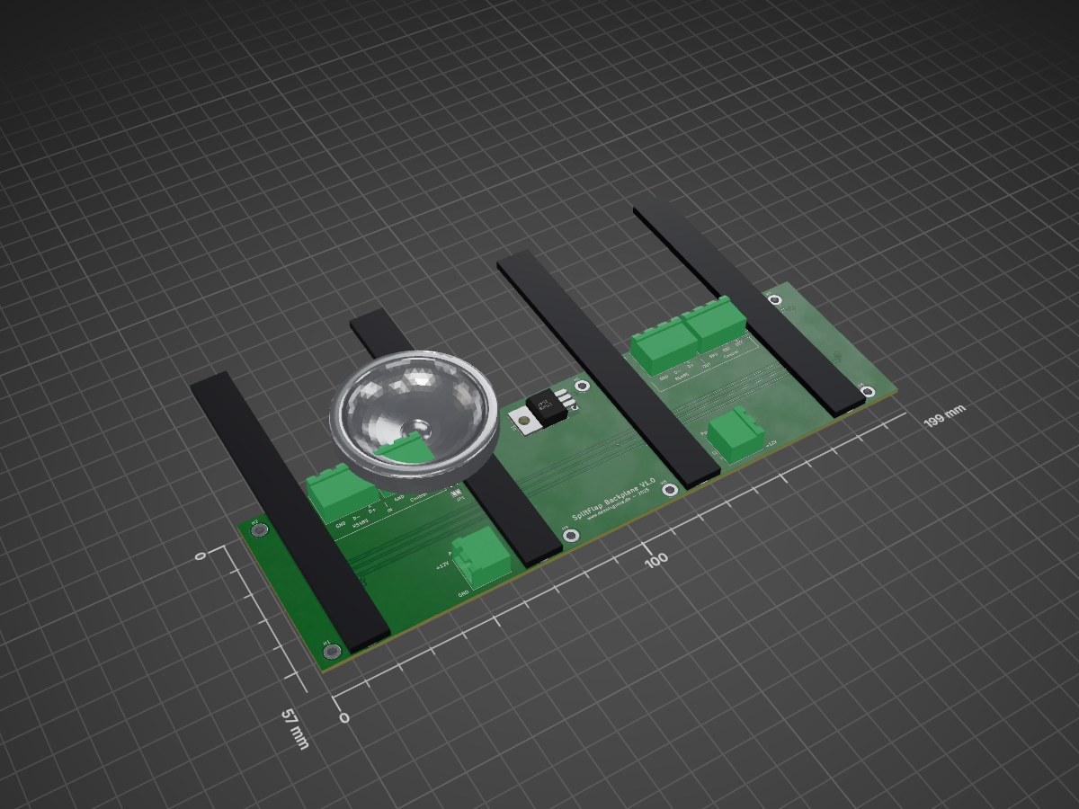
Splitflap backplane is an open-source printed circuit board by dennis9819, from the dennis9819/split-flap-controller repository on GitHub, published under the AGPL-3.0 licence. It is a 2-layer board of 199 × 57 mm with 21 parts on 24 nets, routed with 188 tracks and 28 vias.
It is built around the 74AHCT1G125SE and L7805. Its parts include 6 connectors and 2 ICs. It belongs with the lEDs and displays boards of this library.


Welcome to split-flap-controller, the firmware + hardware design for driving a modular, scalable split-flap display system.

Development of this project began in 2024 with the goal of creating a robust, DIY split-flap display that anyone can build and customize themselves. Inspired by the iconic Frankfurt Airport display, this project aims to recreate the nostalgic mechanical aesthetic and characteristic flipping sound that made those displays so memorable.
Ongoing Project! This repository is not final.
This display is designed in Fusion360. All schematics and boards are designed in KiCAD 9.
Most parts can be 3d printed. The modular backpanel needs to be fabricated from sheetmetal. You can use suppliers like JLCPCB for manufacturing or design a different 3d printable solution.
If you want to generate custom flaps, you can find my flap generator here: split-flap-generator
This project is open source and available under the AGPL-3.0 License.
Each Module pulls arround 110mA. This is roughly 1.4W of power. This can be reduced by turning off the motors in idle.
This is a 3D printable, expandable split flap display based on the original design of David Königsmann. This version uses his drum and flap design but completly redesigns the rest of the system.
The firmware as well as the Server is completly rewritten from scratch.
Feel free to checkout his more affordable and diy friendly design.
| Qty | Value | Footprint | References |
|---|---|---|---|
| 8 | MountingHole_Pad | MountingHole:MountingHole_2.7mm_M2.5_DIN965_Pad | H1, H2, H3, H4, H5, H6, H7, H8 |
| 4 | 2x08 Edge Connector | Dennis:Card-Socket Flap Module | JM1, JM2, JM3, JM4 |
| 4 | Conn_01x03 | Connector_Phoenix_MSTB:PhoenixContact_MSTBA_2,5_3-G-5,08_1x03_P5.08mm_Horizontal | J5, J6, J7, J8 |
| 2 | Conn_01x02 | Connector_Phoenix_MSTB:PhoenixContact_MSTBA_2,5_2-G-5,08_1x02_P5.08mm_Horizontal | J1, J2 |
| 1 | 74AHCT1G125 | Package_TO_SOT_SMD:SOT-353_SC-70-5 | U2 |
| 1 | Jumper_2_Open | Jumper:SolderJumper-2_P1.3mm_Open_Pad1.0x1.5mm | JP1 |
| 1 | L7805 | Package_TO_SOT_THT:TO-220-3_Horizontal_TabDown | U1 |
It measures 199 × 57 mm and has 2 copper layers, 1.6 mm thick.
21 parts, built around the 74AHCT1G125SE and L7805. The full list of its parts is on this page, with links to each part's symbol and footprint where PCBKit's library has them.
From the dennis9819/split-flap-controller repository on GitHub, at the commit this page was made from: the board is cad/Schematics/splitflap-backplane/splitflap-backplane.kicad_pcb and its schematic cad/Schematics/module_controller/ModuleController.kicad_sch. PCBKit opens the board in the browser, with nothing to install.
Its repository publishes it under the AGPL-3.0 licence: you may reuse it on that licence's terms (keep the author's notice, and for a copyleft licence share your changes alike).
dennis9819/split-flap-controller
Sourcecode and Schematics for the controller of my split-flap display

dennis9819/split-flap-controller
Sourcecode and Schematics for the controller of my split-flap display


keeos-io/ogham
Ogham — a dual-voice bytebeat synthesizer for Eurorack. Firmware (MIT) and hardware (CC BY-SA 4.0).


wntrblm/Big_Honking_Button
A simple Eurorack sampler and performance module in a silly package.

arturo182/keyboard_featherwing_hw
The Keyboard FeatherWing is an easy way to add a handheld Qwerty keyboard and a 2.6” color display (+ more) to your project! It fits well in your hands and is great for typing with your thumbs, early 2000s-style.

realworldpixel/home-assistant-keypad
A 9-key macro keypad for Home Assistant, running ESPHome. Every key is RGB backlit, and comes in two variants: one that sits on a desk and one that mounts on a wall, with magnets or screws.