4 layers70.6 × 100 mm

 dchwebb/QuadMod3
Eurorack 4 voice effects processor based on STM32H563
AK4619 DevBoard is an open-source printed circuit board by dchwebb, from the dchwebb/QuadMod repository on GitHub. It is a 2-layer board of 72.4 × 98 mm with 74 parts on 155 nets, routed with 519 tracks and 163 vias.
It is built around the AK4619VN and MCP6004-E/P. Its parts include 25 capacitors, 21 resistors, 9 connectors, 4 ICs and 1 inductor. It belongs with the microcontroller boards and audio and music boards of this library.


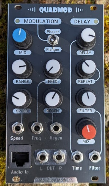
Quadmod is a Eurorack modular four channel effect module. A modulation section allows either phasing or flanging followed by a delay. As part of the Mountjoy Modular polyphonic range the module uses a series of intermodulation paths to convert a four channel input to a stereo output.
The phaser uses 4 (configurable up to 16) all pass filters to create the phasing effect. Each channel's all pass filter is 45° out of phase with the last. The regeneration (feedback) control progressively mixes one channel to the next to widen the stereo spectrum.
The flanger uses multiple short modulated delays to create a flanger/chorus effect. The delay times are modulated with a 45° phase shift from channel to channel. A wide option (on by default) mixes a further 180° phase shifted version of each channel's signal to the next channel.
Quadmod uses an STM32563 microcontroller which controls a four channel Audio Codec (AsahiKasei AK4619) using SPI for configuration and SAI (Serial Ausio Interface) peripheral to manage the 4 in and 4 out I2S audio streams. The microcontroller reads the front panel controls with internal 12 bit ADCs.
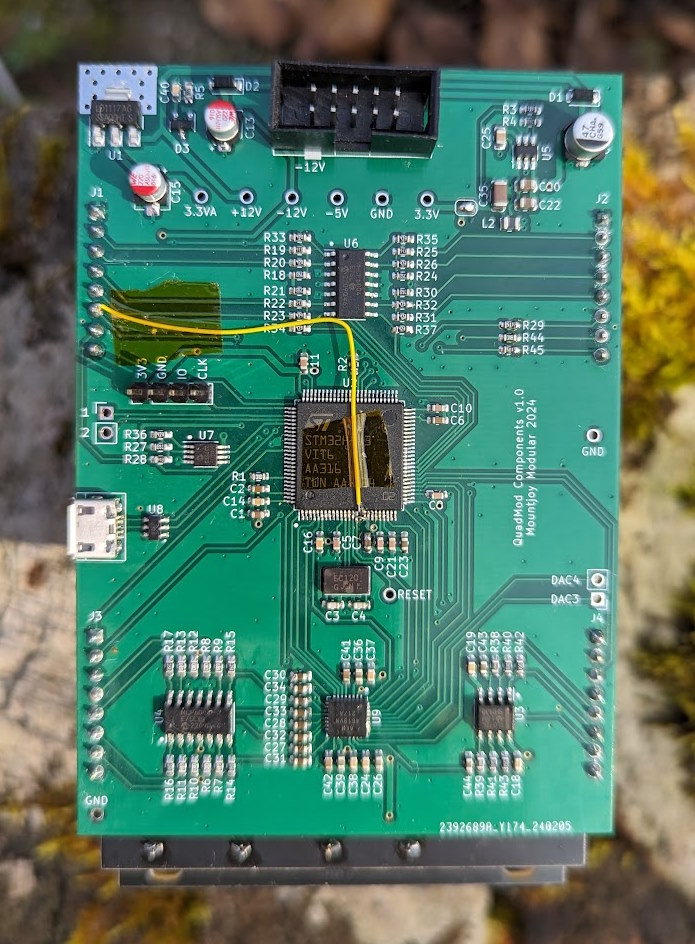
A USB socket is provided for serial configuration and a web editor using WebSerial provides a UI for editing settings. Three LEDs are controlled with PWM from the MCU to indicate modulation LFO rates and delay times.
Construction is a sandwich of three PCBs with a component board, a controls board and a panel. PCBs designed in Kicad v7.
In addition the the Eurorack +/-12V rails (which have polarity protection and filtering) a digital 3.3v rail is supplied using a TI TPS561201 and analog 3.3v is generated with an LM1117-3.3.
Version 1 of the component PCB had microcontroller pins PC0 (SAI2_SD_A) and PC1 (DLY_TIME_POT) flipped.
| Qty | Value | Footprint | References |
|---|---|---|---|
| 12 | 1uF | Capacitor_SMD:C_0603_1608Metric_Pad1.08x0.95mm_HandSolder | C5, C6, C7, C8, C9, C10, C11, C12, C20, C21, C22, C23 |
| 12 | Jumper_NC_Small | Jumper:SolderJumper-2_P1.3mm_Bridged_RoundedPad1.0x1.5mm | JP1, JP2, JP3, JP4, JP5, JP6, JP7, JP8, JP9, JP10, JP11, JP12 |
| 8 | 100nF | Capacitor_SMD:C_0603_1608Metric_Pad1.08x0.95mm_HandSolder | C1, C2, C3, C13, C14, C16, C17, C18 |
| 8 | 14k | Resistor_SMD:R_0603_1608Metric_Pad0.98x0.95mm_HandSolder | R10, R11, R12, R13, R18, R19, R20, R21 |
| 5 | 10k | Resistor_SMD:R_0603_1608Metric_Pad0.98x0.95mm_HandSolder | R1, R14, R15, R16, R17 |
| 4 | 100k | Resistor_SMD:R_0603_1608Metric_Pad0.98x0.95mm_HandSolder | R2, R4, R6, R8 |
| 4 | 68k | Resistor_SMD:R_0603_1608Metric_Pad0.98x0.95mm_HandSolder | R3, R5, R7, R9 |
| 3 | 10uF | Capacitor_SMD:C_0603_1608Metric_Pad1.08x0.95mm_HandSolder | C4, C15, C19 |
| 2 | 2.2uF | Capacitor_SMD:C_0603_1608Metric_Pad1.08x0.95mm_HandSolder | C24, C25 |
| 2 | TestPoint | Custom_Footprints:1mm_Test_Point | TP1, TP2 |
| 1 | AK4619VN | Custom_Footprints:QFN-32-1EP_5x5mm_P0.5mm_EP3.1x3.1mm_ThermalVias | U4 |
| 1 | Conn_02x08_Odd_Even | Connector_PinHeader_2.54mm:PinHeader_2x08_P2.54mm_Vertical | J6 |
| 1 | Conn_02x10_Odd_Even | Connector_PinHeader_2.54mm:PinHeader_2x10_P2.54mm_Vertical | J8 |
| 1 | Conn_02x15_Odd_Even | Connector_PinHeader_2.54mm:PinHeader_2x15_P2.54mm_Vertical | J7 |
| 1 | Conn_02x17_Odd_Even | Connector_PinHeader_2.54mm:PinHeader_2x17_P2.54mm_Vertical | J9 |
| 1 | Hyperram_BGA | Custom_Footprints:BGA-24_5x5_6.0x8.0mm | U3 |
| 1 | In | Connector_PinSocket_2.54mm:PinSocket_1x04_P2.54mm_Vertical | J3 |
| 1 | L_Small | Inductor_SMD:L_0603_1608Metric_Pad1.05x0.95mm_HandSolder | L1 |
| 1 | MCP6004 | Package_SO:SO-14_3.9x8.65mm_P1.27mm | U2 |
| 1 | Out | Connector_PinSocket_2.54mm:PinSocket_1x04_P2.54mm_Vertical | J4 |
| 1 | Out_Amp | Connector_PinSocket_2.54mm:PinSocket_1x04_P2.54mm_Vertical | J5 |
| 1 | Power | Connector_PinSocket_2.54mm:PinSocket_1x03_P2.54mm_Vertical | J1 |
| 1 | Power | Connector_PinSocket_2.54mm:PinSocket_1x02_P2.54mm_Vertical | J2 |
| 1 | TL074 | Package_SO:SO-14_3.9x8.65mm_P1.27mm | U1 |
It measures 72.4 × 98 mm and has 2 copper layers, 1.6 mm thick.
74 parts, built around the AK4619VN and MCP6004-E/P. The full list of its parts is on this page, with links to each part's symbol and footprint where PCBKit's library has them.
From the dchwebb/QuadMod repository on GitHub, at the commit this page was made from: the board is Hardware/AK4619_DevBoard.kicad_pcb and its schematic Hardware/AK4619_DevBoard.kicad_sch. PCBKit opens the board in the browser, with nothing to install.
Its repository states no licence, so its author keeps all rights: ask dchwebb before reusing the design.


shabaz123/Vectorscope_GuyFawkes
A reimplementation of the Vectorscope from https://github.com/Hack-a-Day/Vectorscope


apfaudio/eurorack-pmod
A eurorack-friendly audio frontend compatible with many FPGA boards, based on the AK4619VN audio CODEC.


bkshepherd/DaisySeedProjects
A collection of hardware and software projects based around the Electro-Smith Daisy Seed

Neumi/open_echo
Open Source echo sounder / depth sounder / SONAR for bathymetry and research. Arduino based and compatible.