2 layers244 × 244 mm
 danwerner21/we816-mark21
WE816 PC Mark/2
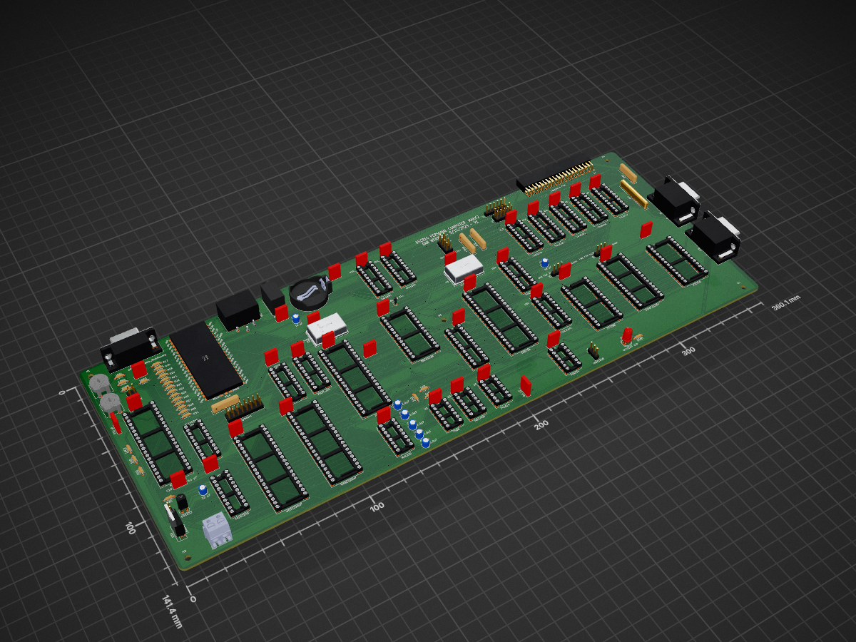
We816-mark2 is an open-source printed circuit board by danwerner21, from the danwerner21/we816-mark2 repository on GitHub. It is a 2-layer board of 360.1 × 141.4 mm with 136 parts on 328 nets, routed with 5,905 tracks and 317 vias.
It is built around the 74LS245SC, 74LVC245AD and MAX232N, with the 27C256-17/J, 74AC04PC and 74LS14PC among its other parts. Its parts include 44 capacitors, 31 ICs, 26 resistors, 15 connectors and 4 crystals. It belongs with the RP2040 and FPGA and CPLD boards of this library.


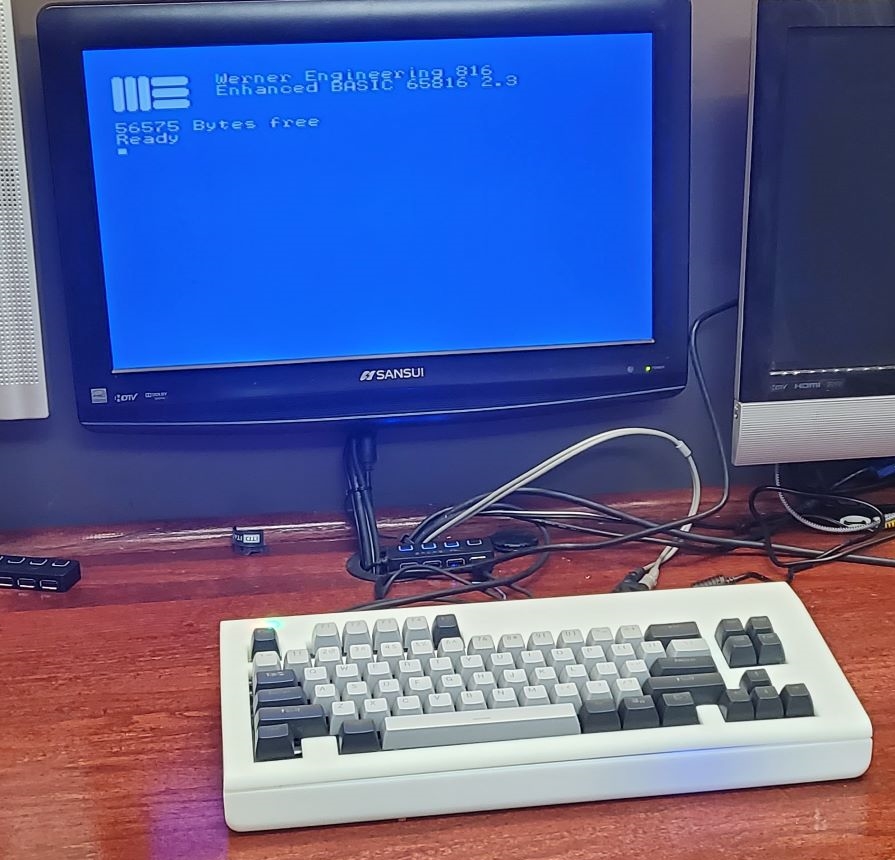
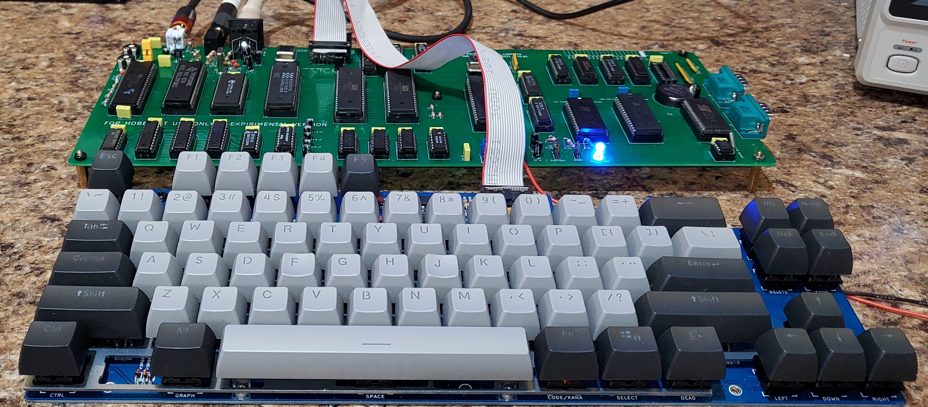
The WE816-MARK2 is the second iteration of a 16-bit 65816 based system with 512K of System RAM, 96K of System ROM, a Raspberry PI Pico based graphics processor and an AY-3-8910 Sound chip. The system runs a custom version of BASIC and supports commodore compatible IEC disk drives.
EhBASIC by Lee Davison was ported to the 65816 CPU on the WE816 computer. It is designed to allow a full 64K bank for BASIC code and variables with the BASIC interpreter running in a totally different bank. Full documentation on the basic intrepreter can be found in the support folder
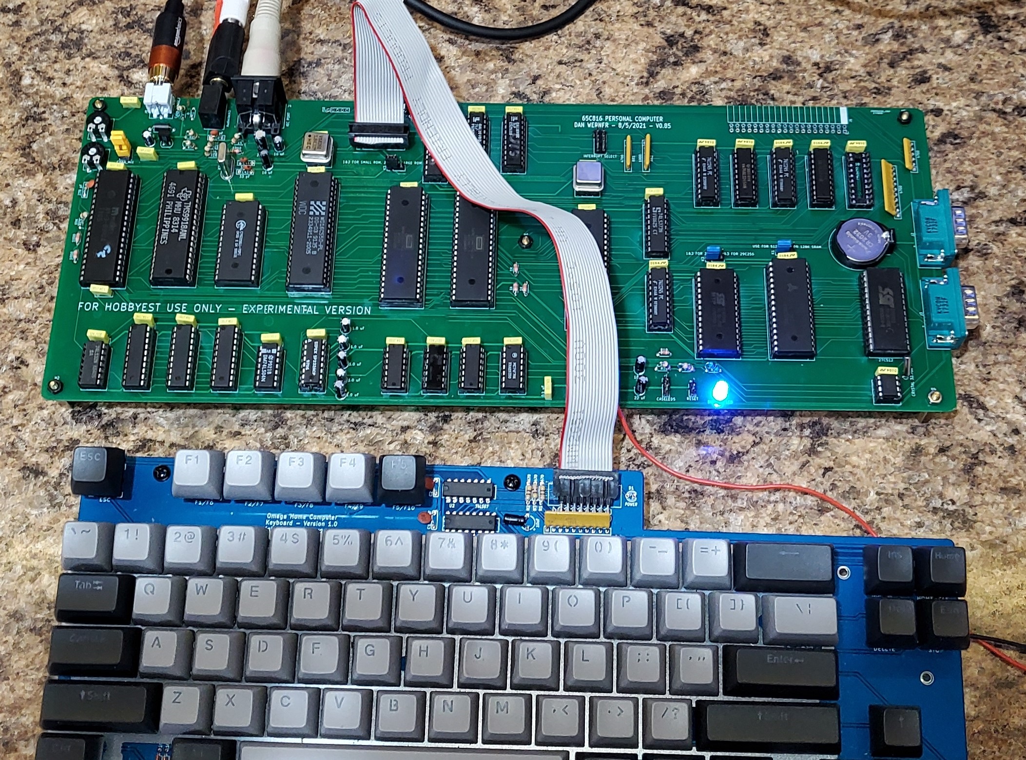
V0.08 board U13 should be a 22V10 rather than a 20V8 (no patches required) U31 should be 74ALS245 rather than 74AC245 (no patches required) The Footprints for the expansion(J7) and Keyboard(J3) connectors are wrong -- special cables are required to connect this version to keyboard and expansion RTC IS STILL BROKEN, DO NOT POPULATE U7,U8,X3,C36,C37,C34,R1,R2,R3,U9,BT1,K4,JP1, & JP2
V0.9 board U16 should not be populated -- the wait state generator is not functional, maximum successful tested clock speed is 2.4576 Mhz Higher CPU speeds are possible, but the video will not function at much beyond this speed.
As of this time, the repo includes
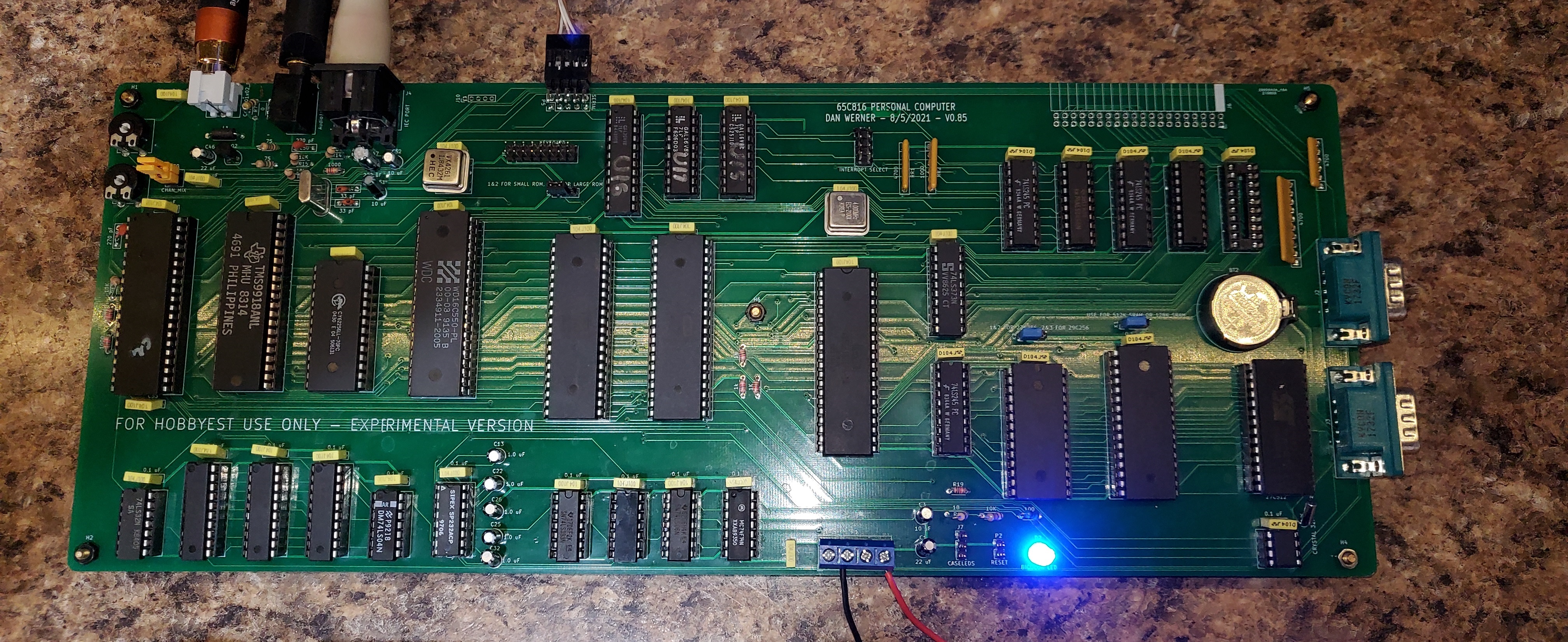
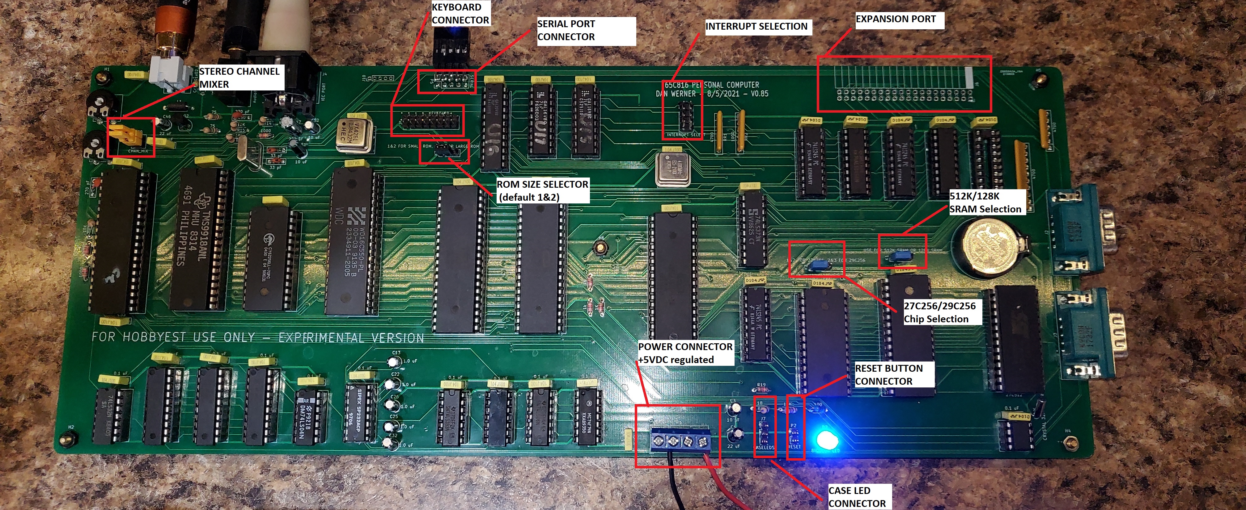
Jumper P9 -- stereo channel mixer
Jumper K1 - SRAM chip selection
Jumper K2 - ROM chip selection
Jumper K3 - ROM size
Power P1
Reset P2
Jumper J1, Interrupt Select

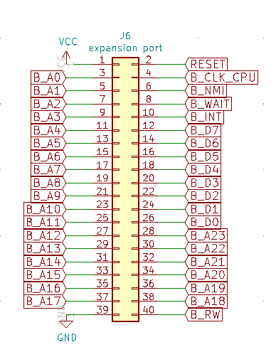
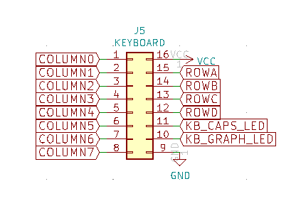
IO PORTS
| Address | Description | Value | Value |
|---|---|---|---|
| $fe30 | Scan Line Emulation | on | off |
| $fe31 | Display Page | page 0 | page 1 |
| $fe32 | character generator write offset | write offset | |
| $fe33 | character generator write | Value | |
| $fe34 | device command | Command | |
| $fe35 | Text Mode | on | off |
| $fe36 | Lores Mode | on | off |
| $fe37 | Double Lores Mode (must be in lores first) | on | off |
| $fe38 | Hires Mode | on | off |
| $fe39 | Double Hires Mode (must be in hires first) | on | off |
| $fe3A | 80 Col Mode (must be in text mode) | on | off |
| $fe3b | Mixed Mode (must be in lores/hires first) | on | off |
| $fe3c | Quad Hires (must be in hires first) | on | off |
| $fe3d | Mono Hires (must be in hires first) | on | off |
| Qty | Reference(s) | Value |
|---|
The Keyboard used in the WE816 is identical to the keyboard used in Sergey Kiselev's MSX compatible OMEGA computer. See the Schematics, PCB layout and build instructions here
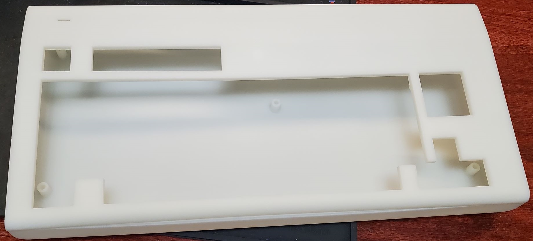
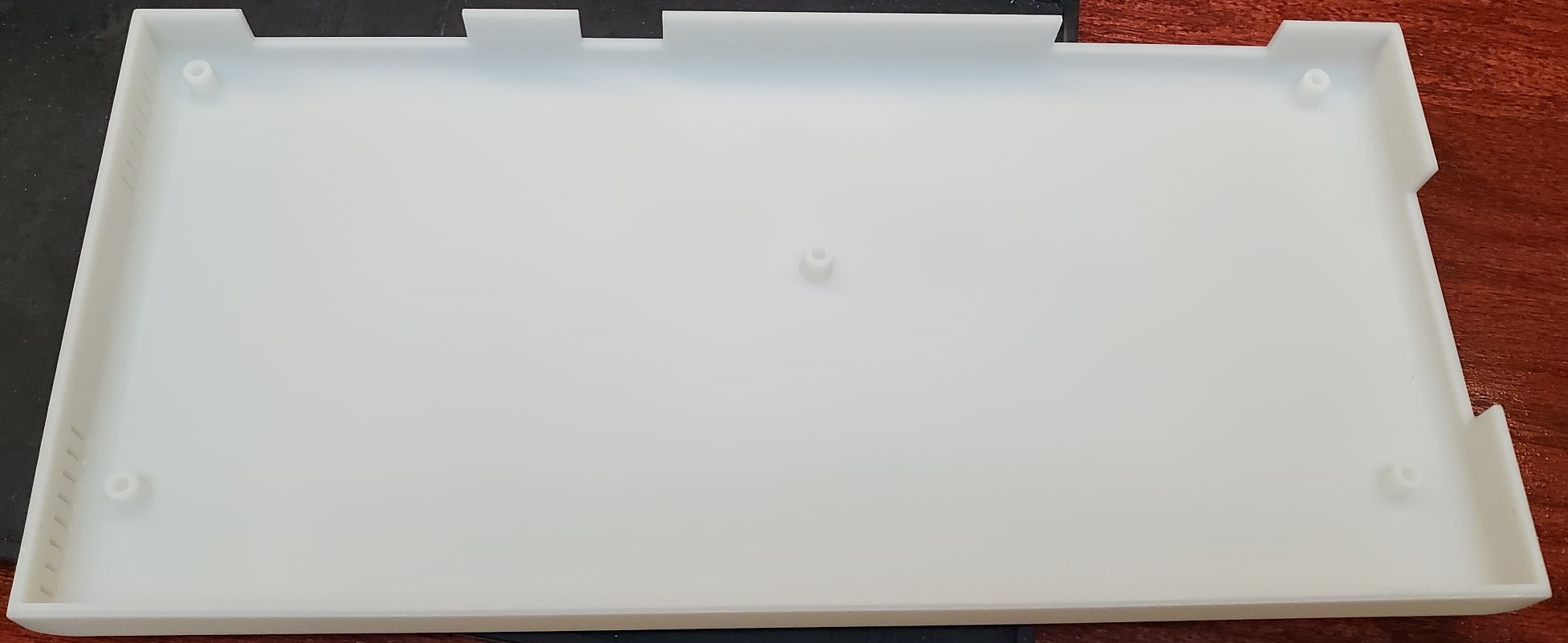
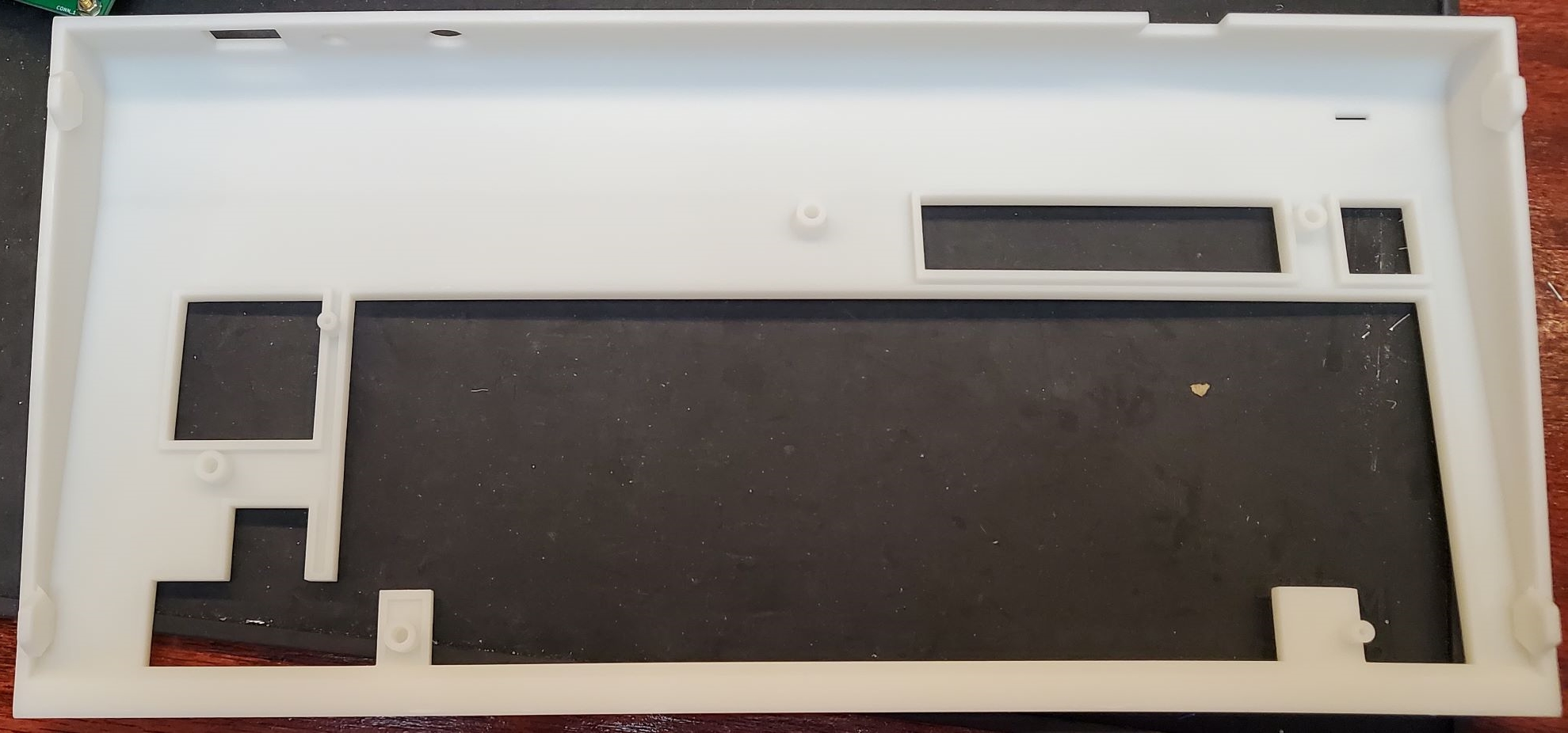
The case in the following images is a 3D print manufactured by the 3D print service offered by JLCPCB.com. The case was originally designed to be 3D printed by a FDM printer such as the Anycubic Chiron. It was originally intended that threaded inserts be melted into the stand off posts so the diameter of the holes were sized accordingly. If a printing service (such as JLCPCB) is used that uses resin printing, it is necessary to slightly drill out the holes in the stand offs so that threaded inserts can be glued in. It should also be noted that the design tolerances are quite tight and variations in printing can mean that some slight adjusting may be needed in order to get a good fit.
A 12V to 5V converter can be seen in the image that was added into the case in order to convert the 12V power input to the 5B required by the main board.
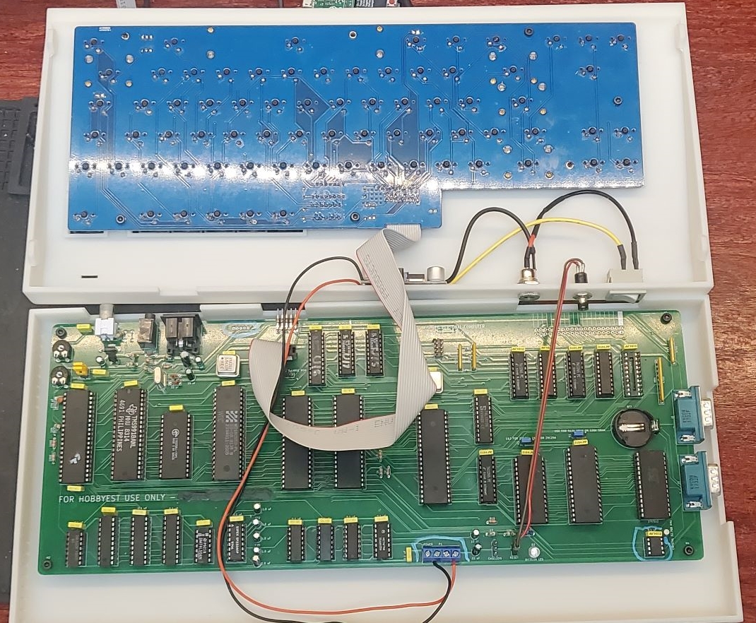
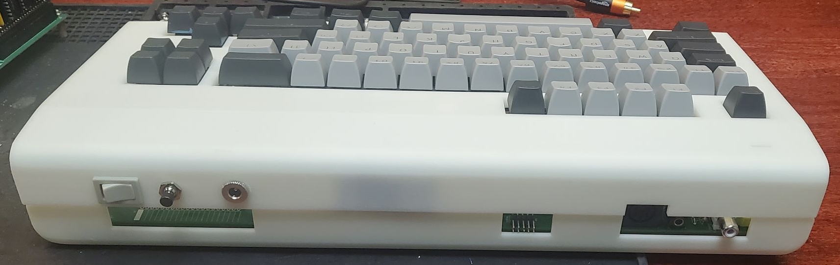
If there are any questions, I can be reached at vic2020Dan at gmail dot com.
| Qty | Value | Footprint | References |
|---|---|---|---|
| 34 | 0.1 µF | Capacitor_THT:C_Rect_L7.0mm_W2.0mm_P5.00mm | C1, C2, C10, C11, C12, C13, C14, C15, C16, C17, C18, C19, C20, C21, C22, C23 +18 |
| 9 | 1KΩ | Resistor_THT:R_Axial_DIN0204_L3.6mm_D1.6mm_P5.08mm_Horizontal | R5, R6, R7, R8, R9, R10, R17, R18, R19 |
| 5 | 1.0µF | Capacitor_THT:CP_Radial_D4.0mm_P2.00mm | C39, C40, C41, C42, C43 |
| 5 | MountingHole | MountingHole:MountingHole_3.2mm_M3 | H1, H2, H3, H4, H5 |
| 4 | 10KΩ | Resistor_THT:R_Axial_DIN0204_L3.6mm_D1.6mm_P5.08mm_Horizontal | R11, R12, R13, R14 |
| 4 | 74LS245 | Package_DIP:DIP-20_W7.62mm_Socket_LongPads | U20, U22, U23, U24 |
| 3 | 1K | Resistor_THT:R_Axial_DIN0204_L3.6mm_D1.6mm_P5.08mm_Horizontal | R21, R24, R27 |
| 3 | 2K | Resistor_THT:R_Axial_DIN0204_L3.6mm_D1.6mm_P5.08mm_Horizontal | R22, R25, R28 |
| 3 | 510 | Resistor_THT:R_Axial_DIN0204_L3.6mm_D1.6mm_P5.08mm_Horizontal | R20, R23, R26 |
| 3 | 74LVC245 | Package_DIP:DIP-20_W7.62mm_Socket_LongPads | U32, U33, U34 |
| 3 | GAL16V8 | Package_DIP:DIP-20_W7.62mm_Socket_LongPads | U6, U12, U14 |
| 2 | 10 µF | Capacitor_THT:CP_Radial_D4.0mm_P2.00mm | C46, C47 |
| 2 | 270 pF | Capacitor_THT:C_Rect_L7.0mm_W2.0mm_P5.00mm | C44, C45 |
| 2 | 47 | Resistor_THT:R_Axial_DIN0204_L3.6mm_D1.6mm_P5.08mm_Horizontal | R29, R31 |
| 2 | 4700Ω | Resistor_THT:R_Array_SIP6 | RR2, RR3 |
| 2 | 4700Ω | Potentiometer_THT:Potentiometer_ACP_CA9-V10_Vertical | RV1, RV2 |
| 2 | CXO_DIP14 | Oscillator:Oscillator_DIP-14 | X1, X4 |
| 2 | DB9_Male | Connector_Dsub:DSUB-9_Male_Horizontal_P2.77x2.84mm_EdgePinOffset9.90mm_Housed_MountingHolesOffset11.32mm | J9, J10 |
| 2 | W65C22NxP | Package_DIP:DIP-40_W15.24mm_Socket_LongPads | U1, U5 |
| 1 | 1&2 FOR 27C256, 2&3 FOR 29C256 | Connector_PinHeader_2.54mm:PinHeader_1x03_P2.54mm_Vertical | K3 |
| 1 | 100Ω | Resistor_THT:R_Axial_DIN0204_L3.6mm_D1.6mm_P5.08mm_Horizontal | R15 |
| 1 | 10K | Resistor_THT:R_Array_SIP6 | RN1 |
| 1 | 10Ω | Resistor_THT:R_Axial_DIN0204_L3.6mm_D1.6mm_P5.08mm_Horizontal | R4 |
| 1 | 16550 | Package_DIP:DIP-40_W15.24mm_Socket_LongPads | U15 |
| 1 | 1KΩ | Resistor_THT:R_Array_SIP6 | RR1 |
| 1 | 22 µF | Capacitor_THT:CP_Radial_D4.0mm_P2.00mm | C35 |
| 1 | 27C256 | Package_DIP:DIP-28_W15.24mm_Socket_LongPads | U28 |
| 1 | 27C512 | Package_DIP:DIP-28_W15.24mm_Socket_LongPads | U29 |
| 1 | 4700Ω | Resistor_THT:R_Array_SIP10 | RR4 |
| 1 | 658C16 | Package_DIP:DIP-40_W15.24mm_Socket_LongPads | U11 |
| 1 | 7406 | Package_DIP:DIP-14_W7.62mm_Socket_LongPads | U2 |
| 1 | 74AC04 | Package_DIP:DIP-14_W7.62mm_Socket_LongPads | U10 |
| 1 | 74ALS245 | Package_DIP:DIP-20_W7.62mm_Socket_LongPads | U31 |
| 1 | 74ALS373 | Package_DIP:DIP-20_W7.62mm_Socket_LongPads | U30 |
| 1 | 74LS06N | Package_DIP:DIP-14_W7.62mm_Socket_LongPads | U3 |
| 1 | 74LS14 | Package_DIP:DIP-14_W7.62mm_Socket_LongPads | U4 |
| 1 | 74LS244 | Package_DIP:DIP-20_W7.62mm_Socket_LongPads | U21 |
| 1 | ATF22V10 | Package_DIP:DIP-24_W7.62mm_Socket_LongPads | U13 |
| 1 | AY-3-8910 | Package_DIP:DIP-40_W15.24mm_Socket_LongPads | U25 |
| 1 | AudioJack3 | Connector_Audio:Jack_3.5mm_CUI_SJ1-3533NG_Horizontal_CircularHoles | J1 |
| 1 | BICOLOR LED | LED_THT:LED_D5.0mm | D1 |
| 1 | Battery_Cell | CUSTOMLibrary:Battery_Holder_Coin_2032_BS-7_FIXED | BT2 |
| 1 | CASELEDS | Connector_PinHeader_2.54mm:PinHeader_1x03_P2.54mm_Vertical | J5 |
| 1 | CHAN_MIX | Connector_PinHeader_2.54mm:PinHeader_2x02_P2.54mm_Vertical | P2 |
| 1 | CLK_CPU | Oscillator:Oscillator_DIP-8 | P5 |
| 1 | CRYSTAL 32.768 KHz | Crystal:Crystal_Round_D1.5mm_Vertical | X3 |
| 1 | CXO_DIP8 | Oscillator:Oscillator_DIP-8 | X2 |
| 1 | DE15_Receptacle_HighDensity | Connector_Dsub:DSUB-15-HD_Female_Horizontal_P2.29x1.98mm_EdgePinOffset3.03mm_Housed_MountingHolesOffset4.94mm | J11 |
| 1 | DS1233 | Package_TO_SOT_THT:TO-92L_HandSolder | U37 |
| 1 | DS1501WN | Package_DIP:DIP-28_W15.24mm_Socket_LongPads | U19 |
| 1 | Expansion Port | Connector_PinSocket_2.54mm:PinSocket_2x20_P2.54mm_Horizontal | J7 |
| 1 | IEC PORT | CUSTOMLibrary:din6 | J4 |
| 1 | INTERRUPT SELECT | Connector_PinHeader_2.54mm:PinHeader_2x04_P2.54mm_Vertical | J6 |
| 1 | Keyboard | Connector_PinHeader_2.54mm:PinHeader_2x08_P2.54mm_Vertical | J3 |
| 1 | LM3940 | Package_TO_SOT_THT:TO-220-3_Vertical | U35 |
| 1 | MAX232 | Package_DIP:DIP-16_W7.62mm_Socket_LongPads | U17 |
| 1 | POWER | TerminalBlock_RND:TerminalBlock_RND_205-00001_1x02_P5.00mm_Horizontal | P3 |
| 1 | Pico | RPi:RPi_Pico_SMD_TH | U36 |
| 1 | RESET | Connector_PinHeader_2.54mm:PinHeader_1x02_P2.54mm_Vertical | P4 |
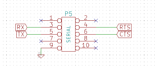
| 1 | SERIAL | Connector_PinHeader_2.54mm:PinHeader_2x05_P2.54mm_Vertical | P1 |
| 1 | SRAM_512KO | Package_DIP:DIP-32_W15.24mm_Socket_LongPads | U26 |
| 1 | TTL Serial | Connector_PinHeader_2.54mm:PinHeader_1x06_P2.54mm_Vertical | J2 |
| 1 | USE FOR 512K SRAM OR 128K SRAM | Connector_PinHeader_2.54mm:PinHeader_1x03_P2.54mm_Vertical | K2 |

lynchaj/duodyne
Duodyne is a hobbyist retrocomputer system designed to run ROMWBW. It is comprised of modules on a system bus


danwerner21/CortexPC
Powertran Cortex clone. PC formfactor, based on Stuart Conner's MiniCortex

raymondh2/CompaqPortableIII
Current PCB Memory Expansion board layout is untested. The backplane for the expansion cards is tested and working.

lynchaj/rhyophyre
Single Board Computer featuring Zilog Z180 processor and NEC µPD7220 Graphics Display Controller


roberto314/EVA-1_Reproduction
Recreation of the very rare K-K Systems EVA-1 Display Adapter for the Epson HX-20 Computer
It measures 360.1 × 141.4 mm and has 2 copper layers, 1.6 mm thick.
136 parts, built around the 74LS245SC, 74LVC245AD, MAX232N and 27C256-17/J. The full list of its parts is on this page, with links to each part's symbol and footprint where PCBKit's library has them.
From the danwerner21/we816-mark2 repository on GitHub, at the commit this page was made from: the board is Hardware/we816mark2.kicad_pcb and its schematic Hardware/file5FFCADA1.kicad_sch. PCBKit opens the board in the browser, with nothing to install.
Its repository states no licence, so its author keeps all rights: ask danwerner21 before reusing the design.