2 layers161.6 × 95.2 mm
Ersaswitch
hb020/ersaswitch
Make a Ersa i-con 1V soldering station work with 2 tools, without re-plugging
80 parts1
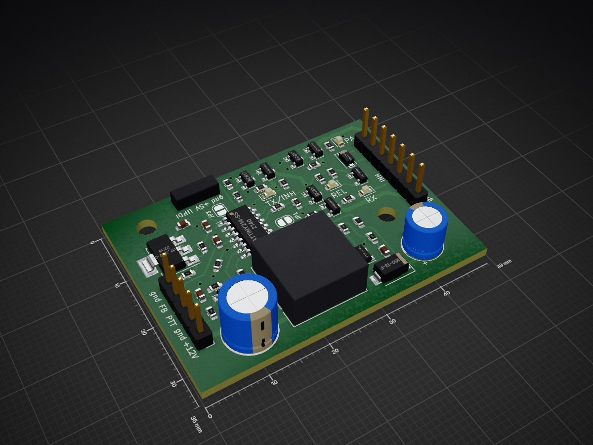
 danupp/boost_sequencer1
Universal sequencer for radio applications with 12 to 28V boost regulator for coaxial relays
Boost sequencer is an open-source printed circuit board by danupp, from the danupp/boost_sequencer repository on GitHub. It is a 2-layer board of 49 × 35 mm with 56 parts on 36 nets, routed with 314 tracks and 23 vias.
It is built around the ATTINY214-SSN, BC817 and PMV65XPER, with the PMV130ENEAR, B160-13-F(MS) and DR127-330-R among its other parts. Its parts include 23 resistors, 9 transistors, 7 capacitors, 6 diodes and 3 connectors. It belongs with the AVR (ATmega, ATtiny) boards of this library.


Universal sequencer for radio applications with 12 to 28V boost regulator for coaxial relays. More info at: sm6vfz.wordpress.com
Changelog/notes:
-Ta bort lödpasta från TPs.
-Schottky: SS16_R1_00001
-PMOS: SI2347DS-T1-GE3
-NMOS: SI2318DS-T1-BE3
-2k2->3k0
Löd alltid relä vid test.
| Qty | Value | Footprint | References |
|---|---|---|---|
| 12 | 33k | Resistor_SMD:R_0603_1608Metric | R1, R5, R6, R7, R8, R9, R10, R12, R19, R20, R21, R22 |
| 4 | BC817 | Package_TO_SOT_SMD:SOT-23 | Q1, Q2, Q3, Q8 |
| 3 | 1n | Capacitor_SMD:C_0603_1608Metric | C5, C6, C8 |
| 3 | 2k2 | Resistor_SMD:R_0603_1608Metric | R13, R14, R23 |
| 3 | PMV65XPE | Package_TO_SOT_SMD:SOT-23 | Q4, Q5, Q9 |
| 3 | SolderJumper_2_Open | Jumper:SolderJumper-2_P1.3mm_Open_RoundedPad1.0x1.5mm | JP1, JP2, JP3 |
| 2 | 100 | Resistor_SMD:R_0603_1608Metric | R11, R15 |
| 2 | 100k | Resistor_SMD:R_0603_1608Metric | R2, R17 |
| 2 | PMV130ENEA | Package_TO_SOT_SMD:SOT-23 | Q6, Q7 |
| 2 | red | LED_SMD:LED_0603_1608Metric | D1, D2 |
| 1 | 100µ/35V | Capacitor_THT:CP_Radial_D6.3mm_P2.50mm | C4 |
| 1 | 10k | Resistor_SMD:R_0603_1608Metric | R18 |
| 1 | 1k | Resistor_SMD:R_0603_1608Metric | R3 |
| 1 | 1µ | Capacitor_SMD:C_0603_1608Metric | C1 |
| 1 | 220p | Capacitor_SMD:C_0603_1608Metric | C3 |
| 1 | 330 | Resistor_SMD:R_0603_1608Metric | R4 |
| 1 | 330µ/25V | Capacitor_THT:CP_Radial_D8.0mm_P3.50mm | C2 |
| 1 | 560 | Resistor_SMD:R_0603_1608Metric | R16 |
| 1 | ATtiny214-SS | Package_SO:SOIC-14_3.9x8.7mm_P1.27mm | U2 |
| 1 | B160-13-F | Diode_SMD:D_SMA | D3 |
| 1 | Conn_01x03_Male | Connector_PinHeader_2.54mm:PinHeader_1x03_P2.54mm_Vertical | J2 |
| 1 | Conn_01x05_Female | Connector_PinHeader_2.54mm:PinHeader_1x05_P2.54mm_Vertical | J1 |
| 1 | Conn_01x07_Female | Connector_PinHeader_2.54mm:PinHeader_1x07_P2.54mm_Vertical | J3 |
| 1 | DR127-330-R | Inductor_SMD:L_12x12mm_H8mm | L1 |
| 1 | LM317_SOT-223 | Package_TO_SOT_SMD:SOT-223-3_TabPin2 | U1 |
| 1 | SM4005PL | Diode_SMD:D_SOD-123F | D5 |
| 1 | green | LED_SMD:LED_0603_1608Metric | D6 |
| 1 | yellow | LED_SMD:LED_0603_1608Metric | D4 |
The 54 most common of 56 parts.
It measures 49 × 35 mm and has 2 copper layers, 1.6 mm thick.
56 parts, built around the ATTINY214-SSN, BC817, PMV65XPER and PMV130ENEAR. The full list of its parts is on this page, with links to each part's symbol and footprint where PCBKit's library has them.
From the danupp/boost_sequencer repository on GitHub, at the commit this page was made from: the board is kicad/boost_sequencer.kicad_pcb. PCBKit opens the board in the browser, with nothing to install.
Its repository states no licence, so its author keeps all rights: ask danupp before reusing the design.
hb020/ersaswitch
Make a Ersa i-con 1V soldering station work with 2 tools, without re-plugging

tomaskovacik/vwcdpic
This is my personal fork of k9spud vwcdpic project

sjgray/CBM-MX-Keyboards
Replacement and enhanced keyboards for Commodore machines

AlxCzl/chipshouter-picoemp-kicad
KiCad port of the PicoEMP electromagnetic fault injection tool, originally designed by NewAE Technology Inc. in Altium.


