2 layers26 × 30 mm
Microcontroller
FrameworkComputer/ExpansionCards
Reference designs and documentation to create Expansion Cards for the Framework Laptop
34 parts1.1kCC-BY-4.0

 dantidote/sphinxmoth18
FPGA interposer that makes flash storage fully work in FireWire iPods (1G/2G): CF or SD, restore, sync, playback. The UDMA-CRC ASIC/PLD that TI's TSB43AA82 reference design called for in 2001.
Ipod cf udma is an open-source printed circuit board by dantidote, from the dantidote/sphinxmoth repository on GitHub, published under the MIT licence. It is a 2-layer board of 53 × 72 mm with 32 parts on 73 nets, routed with 778 tracks and 92 vias.
It is built around the LCMXO2-2000HC-4TG100C and AP2112K-3.3. Its parts include 18 capacitors, 6 connectors, 5 resistors, 2 ICs and 1 diode. It belongs with the fPGA and programmable logic and retro computing and games boards and the FPGA and CPLD boards of this library.


An active FPGA interposer that lets flash storage (CF, or SD behind an adapter) fully replace the 1.8″ hard drive in a 1st/2nd-generation iPod: boot, standalone playback, and full-speed FireWire restore + iTunes sync.
This is the first time in the ~25 years since these iPods shipped that all of that works at once on flash storage. Passive adapters never could, and it turns out they never could have. The reason was documented by Texas Instruments in 2001.
A note on qualifications: I had none. This is the first PCB I've ever had made, I leaned on the autorouter more than any self-respecting layout engineer would admit, and before this project I'd never programmed an FPGA. This board isn't pretty; it was never meant to be. It exists to answer one question: is this possible at all?
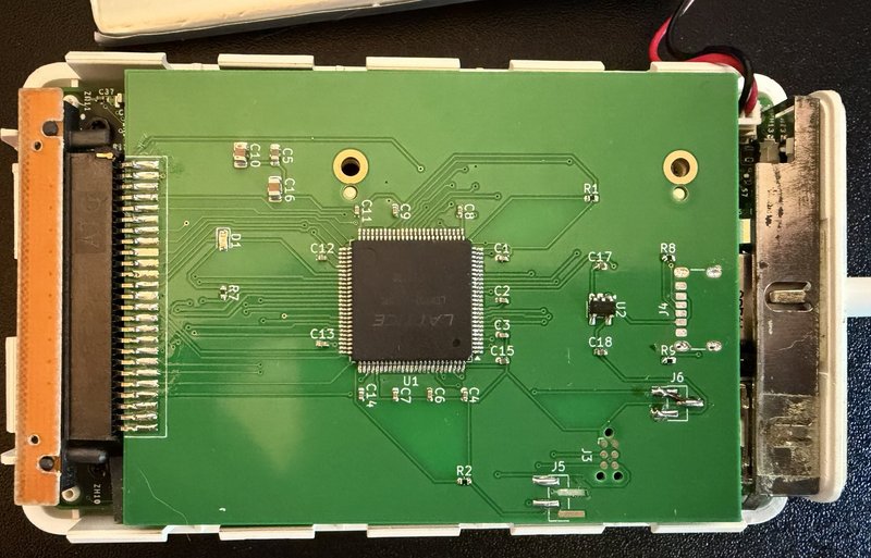 | 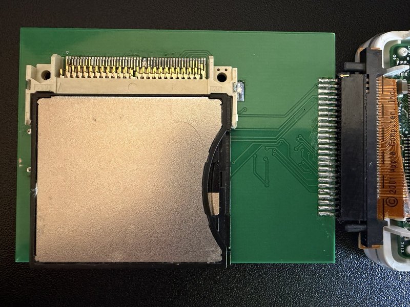 |
The assembled v1 board: FPGA side and CF side. And the point of it all:
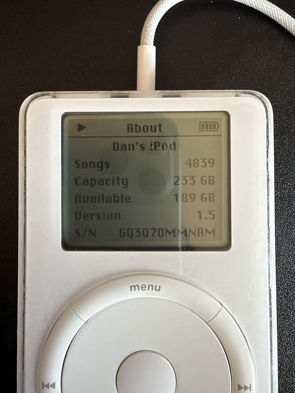
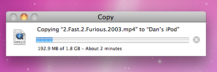
A 1.8 GB file at roughly 15 MB/s over FireWire, through the bridge. No, the 1st gen can't play it. That's not the point.
Sphinxmoth is open source and stays that way: the gerbers, BOM, gateware and a hardware-validated bitstream are all in this repo, under licenses (MIT and CERN-OHL-P-2.0) that let you build your own, and sell them if you want to. Please do.
If you would rather not order a PCB, source a MachXO2, and go find a JTAG probe, I sell pre-assembled, pre-flashed boards at wunkuslabs.com.
FireWire-era iPods (1G/2G, and the 3G) use TI's TSB43AA82 "iSphynxII" FireWire-to-ATA bridge. From TI's own TSB43AA82 Storage Reference Design:
It should be noted that iSphynxII does not implement the 16-bit CRC value required at the end of ATA ultraDMA transfers. There are two ways to deal with this. The first is to use HDDs that allow transfers to continue even if the correct CRC value is not received. The second is to insert an ASIC/PLD between iSphynxII and the HDD that calculates the CRC as the transfer is taking place and drives it to the drive at the appropriate time. This reference design assumes the HDD does not require the CRC.
Apple took TI's first option: the original Toshiba 1.8″ drives tolerate the missing CRC. Every CF card enforces it. So the moment a flash device sees an Ultra-DMA burst from the iSphynxII, it (correctly) rejects the transfer with an interface-CRC error, and no passive adapter can ever fix that, because the CRC simply isn't on the wire.
This project is the "ASIC/PLD between iSphynxII and the HDD" that TI described, built 25 years later. A Lattice MachXO2 sits in the datapath, re-originates every UDMA burst, and supplies the CRC the iSphynxII omits.
But the CRC is only the first wall. Credit to Reddit user SquashHour9940, whose excellent investigation (Further research about flash modified iPod 1st/2nd Gen syncing problem) independently mapped two more layers:
And our bring-up found a fourth layer nobody had hit before, because nobody had gotten this far:
This bridge defeats all four: it originates the missing CRC, rewrites the card's IDENTIFY on the wire (media type and DMA capabilities, per master; a removable or CFA-signature word 0 becomes a classic fixed-disk value, checksum corrected), keeps the DMA path alive at full speed, and gives each of the iPod's two very different bus masters the bus discipline it actually needs. The fixed-disk rewrite has been tested end-to-end with a retail Lexar Professional 800x (32 GB, UDMA 7), the exact card class the community documented as removable-reporting: it restores and syncs through the bridge like any industrial card.
v1 board (CF slot, board/) | Working. Boots, plays, restores, syncs. Reads 19 MB/s, writes 4.6 MB/s over FireWire. Running a 256 GB SD (via FC1307A CF adapter) today. |
| Validated bitstream | releases/v1.0-first-music/ (build outputs are not run-deterministic; this exact binary is the hardware-proven one) |
| v2 (native microSD) | Being considered. microSD would be nice, but at first glance it needs a larger/more expensive FPGA (the v1 XO2-2000 is 89% full and the disk logic moves on-chip; the draft targets an XO2-7000). Exploratory work lives on the v2-native-sd branch: unfabbed, unvalidated, promise-free. Do not build it. |
Tested on: iPod 1st gen (firmware 1.5), Transcend industrial 2 GB CF, FC1307A SD-CF adapter + 256 GB SD, Mac OS X 10.6 + iTunes over FireWire. 2G/3G iPods use the same TSB43AA82 and should work; reports welcome.
Rockbox runs on a Sphinxmoth iPod, with two board-specific wrinkles: the
Rockbox 4.0 release crashes at boot on every 1G/2G (an unaligned store in
the PP5002 scheduler, fixed upstream after 4.0), and Rockbox's stock IDE
timing is too fast for the v1.1-mg132-fix3b bridge image, which adds
about 45 ns to every register read through its PIO synchroniser (init fails
with ATA error: -11 or -32). Newer bridge images pass PIO through the
raw pads and need nothing but the crash fix.
Everything Rockbox-related lives in its own repo: sphinxmoth-rockbox: the ATA driver patch, tested builds for boards already in the field on fix3b, and a workflow that rebuilds them on each upstream Rockbox release. The same files are served from wunkuslabs.com/guide.
The FPGA discovered during bring-up that it serves three masters, and it gives each a different personality:
| Master | How it's detected | What it gets |
|---|---|---|
| iSphynxII (FireWire) | never issues EXECUTE DIAGNOSTIC | Full UDMA2 bridge: bursts re-timed through a FIFO, end-of-burst CRC generated, multi-burst writes, a deliberately "bouncy" flow-control throttle (it abandons bursts on long clean pauses) |
| PP5002 (retail OS) | opens with C90 EXECUTE DIAGNOSTIC | IDENTIFY patched in flight (DMA capability words zeroed, checksum fixed) → the OS falls back to PIO READ/WRITE MULTIPLE through a transparent passthrough |
| CF card | n/a | Always runs UDMA2, regardless of what either host negotiated (SET FEATURES sector-count byte rewritten on the wire) |
Plus the small in-flight surgeries each master demanded: BSY served for status polls mid-command, CS/DA forced idle at the card during bridged bursts, strict data setup/hold on every strobe edge, spec-ordered burst termination, and STANDBY/SLEEP commands rewritten to CHECK POWER MODE (retail cards honor them, then never wake the way the OS expects; the original drive woke transparently). The testbenches encode all of it: the card model sector-terminates, pauses, checks CRC and enforces tSS; the host model parks on the status register, polls, and rings its strobe line. Every cruelty in the sims reproduced a bug first found on real hardware during a two-day, fourteen-bug bring-up.
Or skip it: assembled, flashed and tested boards are for sale.
Board (v1): upload board/ipod-cf-udma-gerbers.zip to any fab (2 layer,
53×72 mm, 1.6 or 0.8 mm). CF socket (J2) is on the BACK; everything else on
the front. board/BOM.csv + board/ipod-cf-udma-pos.csv for assembly.
Bitstream: Lattice Diamond 3.14, cd diamond && pnmainc rebuild.tcl →
impl1/ipodboard_impl1.jed. Or just flash releases/v1.0-first-music/.
Programming: Tag-Connect TC2030-IDC-NL pads (J3, zero height) to any JTAG probe Diamond Programmer / openFPGALoader speaks. The MachXO2 configures from internal flash; program once, done.
Power: bus-powered from the iPod's 3.3 V. J6 shunt selects iPod (1-2) or bench USB-C (2-3); never both. The green LED blips a slow heartbeat when idle and flashes while data is moving through the bridge. The UART header (J5, 115200 8N1) streams the gateware's event log; if something misbehaves, that log is the microscope this whole project was debugged through.
Simulation: Icarus Verilog: cd gateware && iverilog -g2012 -DSIM -I rtl -o wr.vvp sim/tb_full_write.v rtl/*.v && vvp wr.vvp (likewise
tb_full_read.v).
| Path | Contents |
|---|---|
board/ | v1 board: KiCad project, fabbed gerbers, BOM, schematic PDF, DRC/ERC |
gateware/rtl/ | the bridge RTL (interposer_top + engines) |
gateware/sim/ | hardware-calibrated torture testbenches |
diamond/ | Lattice Diamond build project |
releases/ | hardware-validated bitstreams |
v2-native-sd branch | exploratory native-microSD v2: board draft, ata_device/sd_host cores, design doc |
Gateware and software: MIT. Hardware (schematics, board files, gerbers): CERN-OHL-P-2.0. No warranty; a 25-year-old iPod is involved.
| Qty | Value | Footprint | References |
|---|---|---|---|
| 12 | 100nF | Capacitor_SMD:C_0402_1005Metric | C1, C2, C3, C4, C6, C7, C8, C9, C11, C12, C13, C14 |
| 2 | 10k | Resistor_SMD:R_0402_1005Metric | R1, R2 |
| 2 | 10uF | Capacitor_SMD:C_0805_2012Metric | C10, C16 |
| 2 | 1uF | C_0402_1005Metric | C17, C18 |
| 2 | 5.1k | R_0402_1005Metric | R8, R9 |
| 1 | 1uF | Capacitor_SMD:C_0402_1005Metric | C15 |
| 1 | 330R | Resistor_SMD:R_0402_1005Metric | R7 |
| 1 | 4.7uF | Capacitor_SMD:C_0603_1608Metric | C5 |
| 1 | AP2112K-3.3 | SOT-23-5 | U2 |
| 1 | CF socket | Connector_Card:CF-Card_3M_N7E50-E516xx-30 | J2 |
| 1 | LCMXO2-2000HC-4TG100C | Package_QFP:TQFP-100_14x14mm_P0.5mm | U1 |
| 1 | LED | LED_SMD:LED_0603_1608Metric | D1 |
| 1 | PWR_SEL | PinHeader_1x03_P1.27mm_Vertical_SMD_Pin1Left | J6 |
| 1 | TC2030 | Tag-Connect_TC2030-IDC-NL_2x03_P1.27mm_Vertical | J3 |
| 1 | UART | PinHeader_1x04_P1.27mm_Vertical_SMD_Pin1Left | J5 |
| 1 | USB-C | USB_C_Receptacle_GCT_USB4125-xx-x_6P_TopMnt_Horizontal | J4 |
| 1 | iPod 1.8in 50-pin | interposer:iPod_1.8in_50pin | J1 |
It measures 53 × 72 mm and has 2 copper layers, 1.6 mm thick.
32 parts, built around the LCMXO2-2000HC-4TG100C and AP2112K-3.3. The full list of its parts is on this page, with links to each part's symbol and footprint where PCBKit's library has them.
From the dantidote/sphinxmoth repository on GitHub, at the commit this page was made from: the board is board/ipod-cf-udma.kicad_pcb and its schematic board/ipod-cf-udma.kicad_sch. PCBKit opens the board in the browser, with nothing to install.
Its repository publishes it under the MIT licence: you may reuse it on that licence's terms (keep the author's notice, and for a copyleft licence share your changes alike).
FrameworkComputer/ExpansionCards
Reference designs and documentation to create Expansion Cards for the Framework Laptop


DDeGonge/OS-ARM
This arm is not industrial and it will not be fast, but that is not my goal. But it will hopefully be a very nice looking arm fully capable of 6dof motion, cheap enough to keep it accessable but capable enough to…


