2 layers100 × 50 mm
Rc2014-mystorm
electrified/rc2014-mystorm
sigrok-cli --driver saleae-logic16 --config samplerate=20Mhz --channels 0=D0,1=D1,2=D2,3=D3,4=D4,5=D5,6=D6,7=D7,9=RD,10=WR,11=MREQ,13=M1 --samples 1M --output-file z80-fpga
25 parts
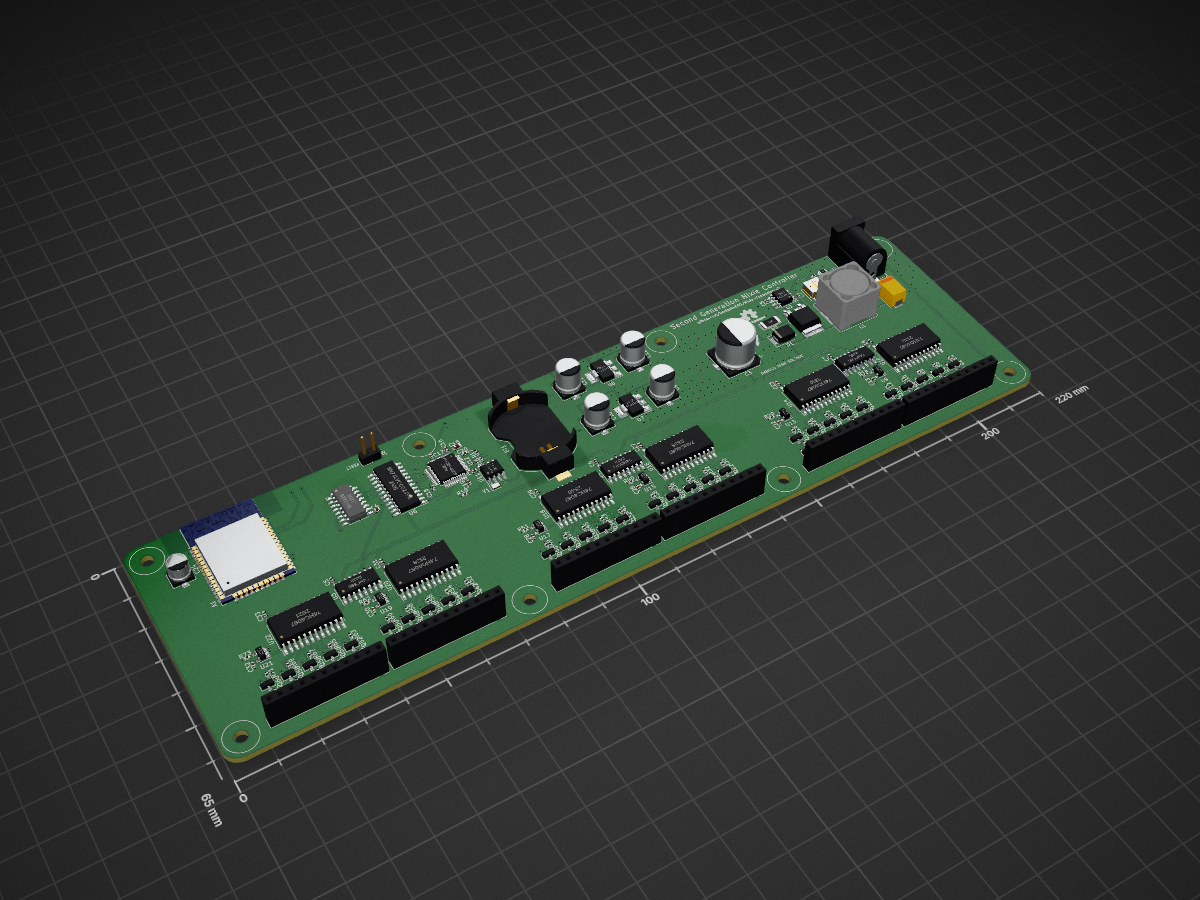
 DanielHeEGG/Nixie-Controller-v22
Second generation universal nixie clock controller
Nixie Controller v2 is an open-source printed circuit board by DanielHeEGG, from the DanielHeEGG/Nixie-Controller-v2 repository on GitHub, published under the CC-BY-SA-4.0 licence. It is a 4-layer board of 220 × 65 mm with 228 parts on 299 nets, routed with 1,373 tracks and 610 vias.
It is built around the STM32F103C8T6, OPA180ID and ESP32-WROOM-32E, with the BH2226F-E2, MAX1771CPA+ and 74HC4067D among its other parts. Its parts include 72 resistors, 61 transistors, 32 capacitors, 22 ICs and 8 connectors. It belongs with the lEDs and displays boards and the ESP32 and STM32 boards of this library.


The most overpowered 6-tube nixie clock controller ever created.
For more details on the project, see Hackaday Page.
Sockets designed to work with this controller are in the NCv2-Sockets repo.
Firmware files are in the NCv2-Firmware repo.
WARNING: This project contains EXPOSED and UNMARKED HIGH VOLTAGE contacts, replicate at your own risk.
This project is licensed under the Creative Commons Attribution-ShareAlike 4.0 International License.
| Qty | Value | Footprint | References |
|---|---|---|---|
| 64 | 6.8K | Resistor_SMD:R_0402_1005Metric | R10, R11, R12, R13, R15, R16, R17, R18, R19, R20, R21, R22, R23, R24, R25, R26 +48 |
| 60 | ~ | Package_TO_SOT_SMD:SOT-23 | Q2, Q10, Q11, Q12, Q13, Q14, Q15, Q16, Q17, Q18, Q19, Q20, Q21, Q22, Q23, Q24 +44 |
| 24 | 100nF | Capacitor_SMD:C_0402_1005Metric | C2, C13, C14, C16, C17, C18, C19, C20, C21, C22, C23, C26, C27, C28, C29, C30 +8 |
| 10 | ~ | TestPoint:TestPoint_Pad_D1.5mm | TP3, TP4, TP5, TP6, TP8, TP9, TP10, TP12, TP13, TP19 |
| 6 | 470 | Resistor_SMD:R_0402_1005Metric | R14, R29, R40, R51, R62, R73 |
| 6 | 74HC4067 | Package_SO:SOIC-24W_7.5x15.4mm_P1.27mm | U10, U14, U16, U18, U20, U22 |
| 6 | OPA180 | Package_TO_SOT_SMD:SOT-23-5 | U9, U13, U15, U17, U19, U21 |
| 6 | ~ | Connector_PinSocket_2.54mm:PinSocket_1x11_P2.54mm_Vertical | J1, J2, J3, J4, J5, J6 |
| 4 | 10uF | Capacitor_SMD:CP_Elec_6.3x7.7 | C9, C10, C11, C12 |
| 3 | 74HC595 | Package_SO:SOIC-16_3.9x9.9mm_P1.27mm | U3, U4, U5 |
| 1 | 0.05 | Resistor_SMD:R_2010_5025Metric | R2 |
| 1 | 1.2M | Resistor_SMD:R_0805_2012Metric | R1 |
| 1 | 100uF | Capacitor_Tantalum_SMD:CP_EIA-7343-43_Kemet-X | C1 |
| 1 | 10uF | Capacitor_SMD:CP_Elec_10x10 | C3 |
| 1 | 12V | TestPoint:TestPoint_Pad_D1.5mm | TP11 |
| 1 | 12V DC JACK | Connector_BarrelJack:BarrelJack_Horizontal | J7 |
| 1 | 180V | TestPoint:TestPoint_Pad_D1.5mm | TP14 |
| 1 | 3.3V | TestPoint:TestPoint_Pad_D1.5mm | TP2 |
| 1 | 32.768KHz | Crystal:Crystal_SMD_2012-2Pin_2.0x1.2mm | Y1 |
| 1 | 4.7uF | Capacitor_SMD:C_0603_1608Metric | C15 |
| 1 | 47uF | Capacitor_SMD:CP_Elec_5x5.3 | C24 |
| 1 | 47uH | Inductor_SMD:L_Bourns_SRR1210A | L1 |
| 1 | 5K | Potentiometer_SMD:Potentiometer_Bourns_3214J_Horizontal | RV1 |
| 1 | 5V | TestPoint:TestPoint_Pad_D1.5mm | TP7 |
| 1 | BACKUP | Battery:BatteryHolder_Keystone_1058_1x2032 | BT1 |
| 1 | BATT | TestPoint:TestPoint_Pad_D1.5mm | TP1 |
| 1 | BH2226 | Package_SO:SOIC-16_4.55x10.3mm_P1.27mm | U2 |
| 1 | ESP32-WROOM-32E | RF_Module:ESP32-WROOM-32 | A1 |
| 1 | GND | TestPoint:TestPoint_Pad_D1.5mm | TP15 |
| 1 | M41T01 | Package_SO:SOIC-8_3.9x4.9mm_P1.27mm | U11 |
| 1 | MAX1771 | Package_SO:SOIC-8_3.9x4.9mm_P1.27mm | U1 |
| 1 | NCP1117-3.3 | Package_TO_SOT_SMD:SOT-223-3_TabPin2 | U8 |
| 1 | NCP1117-5.0 | Package_TO_SOT_SMD:SOT-223-3_TabPin2 | U7 |
| 1 | RST | Connector_PinHeader_2.54mm:PinHeader_1x02_P2.54mm_Vertical | J8 |
| 1 | RTC_CAL | TestPoint:TestPoint_Pad_D1.5mm | TP16 |
| 1 | RX | TestPoint:TestPoint_Pad_D1.5mm | TP18 |
| 1 | SN74LVCC3245A | Package_SO:SO-24_5.3x15mm_P1.27mm | U6 |
| 1 | STM32F103C8 | Package_QFP:LQFP-48_7x7mm_P0.5mm | U12 |
| 1 | TX | TestPoint:TestPoint_Pad_D1.5mm | TP17 |
| 1 | ~ | Package_TO_SOT_SMD:TO-252-2 | Q1 |
| 1 | ~ | Diode_SMD:D_SMB | D1 |
The 220 most common of 228 parts.
It measures 220 × 65 mm and has 4 copper layers, 1.6 mm thick.
228 parts, built around the STM32F103C8T6, OPA180ID, ESP32-WROOM-32E and BH2226F-E2. The full list of its parts is on this page, with links to each part's symbol and footprint where PCBKit's library has them.
From the DanielHeEGG/Nixie-Controller-v2 repository on GitHub, at the commit this page was made from: the board is Nixie-Controller-v2.kicad_pcb and its schematic Nixie-Controller-v2.kicad_sch. PCBKit opens the board in the browser, with nothing to install.
Its repository publishes it under the CC-BY-SA-4.0 licence: you may reuse it on that licence's terms (keep the author's notice, and for a copyleft licence share your changes alike).
electrified/rc2014-mystorm
sigrok-cli --driver saleae-logic16 --config samplerate=20Mhz --channels 0=D0,1=D1,2=D2,3=D3,4=D4,5=D5,6=D6,7=D7,9=RD,10=WR,11=MREQ,13=M1 --samples 1M --output-file z80-fpga


alxhoff/Nixie-tube-clock
Firmware for a nixie tube clock based on STM32 hal libraries

oomlout/oomlout_oomp_project_bot_v_2

dm2lct/tlnixie
PCB files for the Turmlabor nixie clock 2.0


jeffkub/nixie-clock
An open source nixie clock with GPS time synchronization.