4 layers250.4 × 131 mm
Panel-16
geezacoleman/owl-driver-board
Development of a board that receives GPIO input and allows on/off control of connected solenoids.
939 parts14MIT

 danchouzhou/003Clock8
Nuvoton N76E003 / N76S003 MCU digital clock kit.
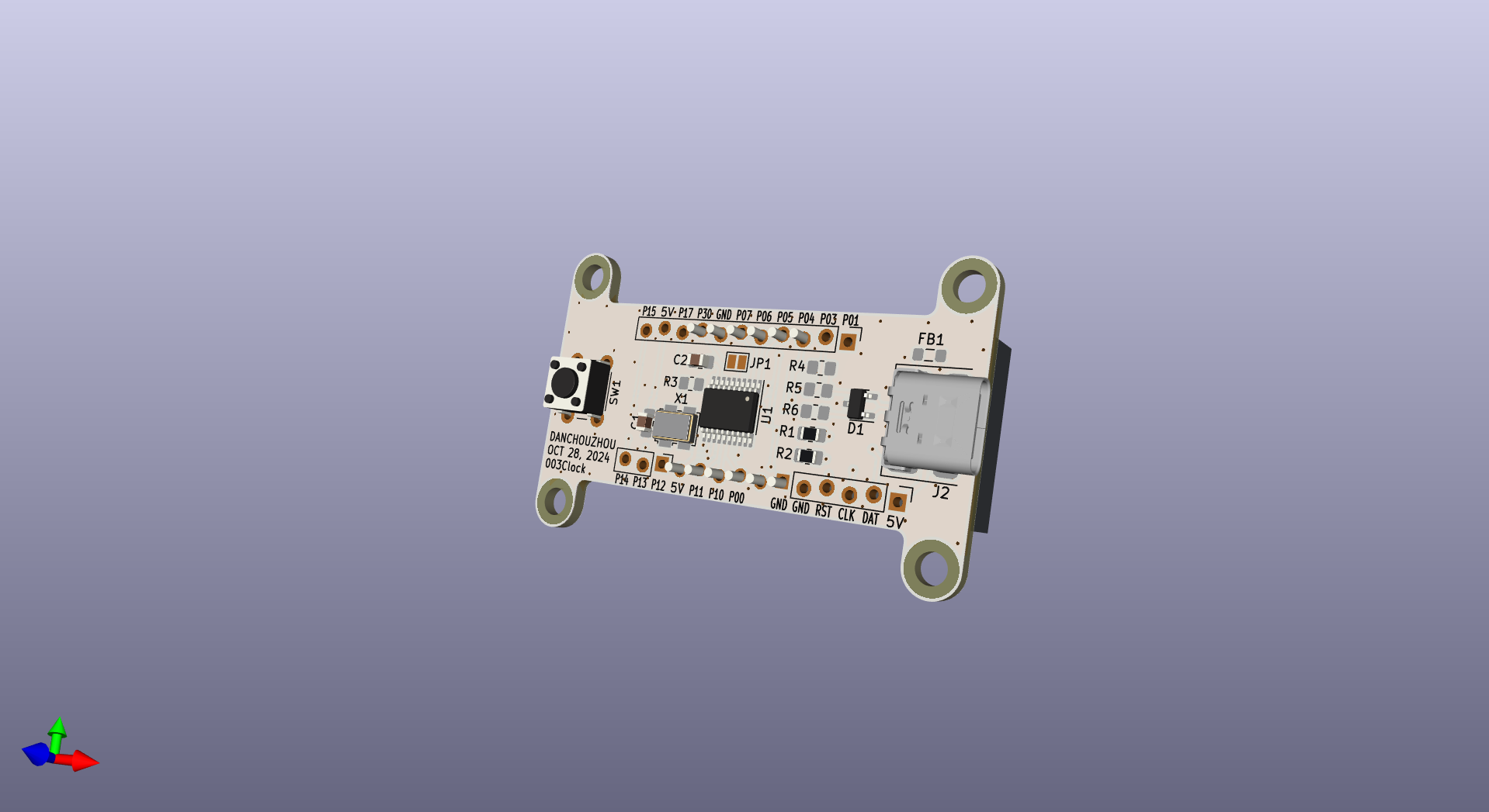
003Clock is an open-source printed circuit board by danchouzhou, from the danchouzhou/003Clock repository on GitHub. It is a 2-layer board of 52.4 × 33 mm with 23 parts on 30 nets, routed with 163 tracks and 94 vias.
It is built around the N76E003AT20 and AZ23C3V3. Its parts include 6 resistors, 4 connectors, 2 capacitors, 2 ICs and 1 diode. It belongs with the 8051 (CH55x, STC, AT89) boards of this library.


This project work with submodule from Nuvoton corporation. You need to initialize submodules by passing --recurse-submodules to the git clone command.
git clone https://github.com/danchouzhou/003Clock.git --recurse-submodulesPlease make sure the installation path is the same as the one in setting.json.
cd firmware/003ClockSimply ./build.bat. main.bin should be inside the Objects folder.
./build.bat./flash.batconnect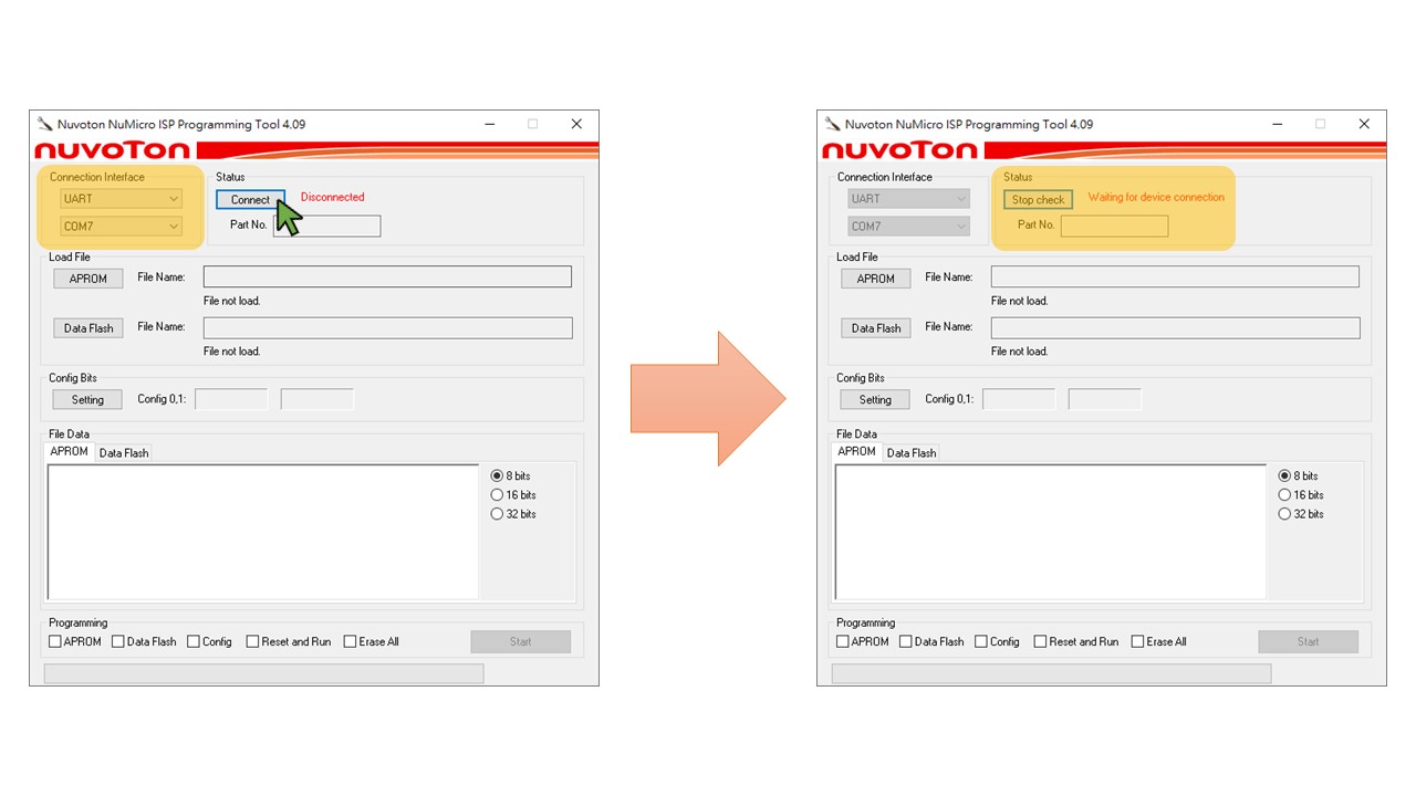
connected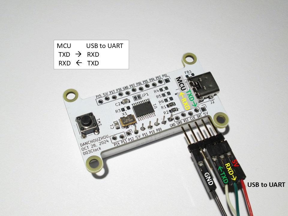
APROM and Reset and Run, then press Start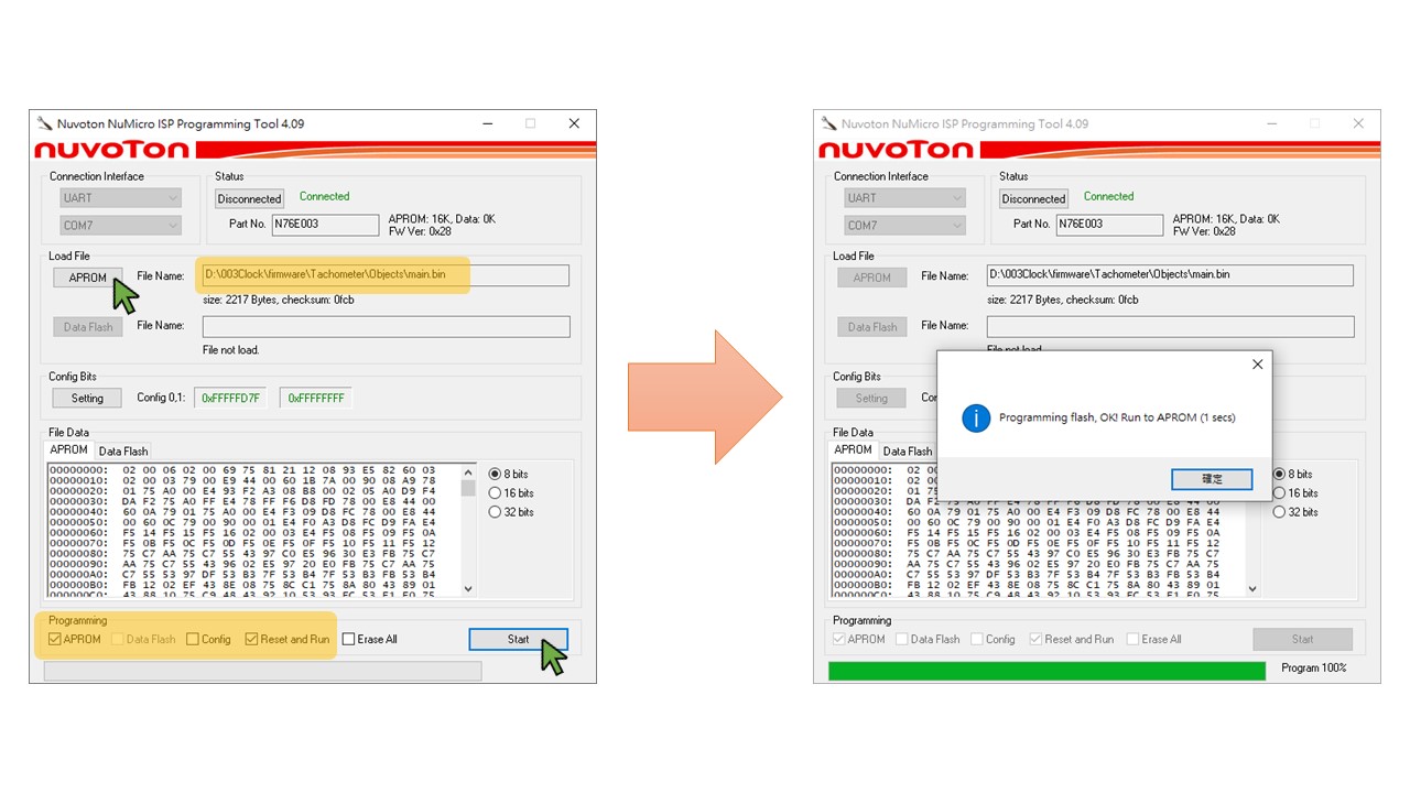
| Qty | Value | Footprint | References |
|---|---|---|---|
| 4 | MountingHole | MountingHole:MountingHole_3.2mm_M3_ISO14580 | H1, H2, H3, H4 |
| 3 | 5.1K | Resistor_SMD:R_0805_2012Metric_Pad1.20x1.40mm_HandSolder | R1, R2, R3 |
| 2 | 1uF | Capacitor_SMD:C_0805_2012Metric_Pad1.18x1.45mm_HandSolder | C1, C2 |
| 2 | 47R | Resistor_SMD:R_0805_2012Metric_Pad1.20x1.40mm_HandSolder | R5, R6 |
| 1 | 1.5K | Resistor_SMD:R_0805_2012Metric_Pad1.20x1.40mm_HandSolder | R4 |
| 1 | 2137160001 | 2137160001:2137160001 | J2 |
| 1 | AZ23C3V3 | Package_TO_SOT_SMD:SOT-23-3 | D1 |
| 1 | Conn_01x03 | Connector_PinHeader_2.54mm:PinHeader_1x03_P2.54mm_Vertical | J4 |
| 1 | Conn_01x05 | Connector_PinHeader_2.54mm:PinHeader_1x05_P2.54mm_Vertical | J3 |
| 1 | Conn_01x11 | Connector_PinHeader_2.54mm:PinHeader_1x11_P2.54mm_Vertical | J1 |
| 1 | FerriteBead_Small | Inductor_SMD:L_0805_2012Metric_Pad1.05x1.20mm_HandSolder | FB1 |
| 1 | LGC-12002 | LGC-12002:LGC-12002 | U2 |
| 1 | N76E003AT20 | Package_SO:TSSOP-20_4.4x6.5mm_P0.65mm | U1 |
| 1 | SG-5032CCN | Oscillator:Oscillator_SMD_SeikoEpson_SG8002LB-4Pin_5.0x3.2mm | X1 |
| 1 | SW_Push | Button_Switch_THT:SW_PUSH_6mm | SW1 |
| 1 | SolderJumper_2_Open | Jumper:SolderJumper-2_P1.3mm_Open_Pad1.0x1.5mm | JP1 |
It measures 52.4 × 33 mm and has 2 copper layers, 1.6 mm thick.
23 parts, built around the N76E003AT20 and AZ23C3V3. The full list of its parts is on this page, with links to each part's symbol and footprint where PCBKit's library has them.
From the danchouzhou/003Clock repository on GitHub, at the commit this page was made from: the board is kicad/003Clock.kicad_pcb and its schematic kicad/003Clock.kicad_sch. PCBKit opens the board in the browser, with nothing to install.
Its repository states no licence, so its author keeps all rights: ask danchouzhou before reusing the design.
geezacoleman/owl-driver-board
Development of a board that receives GPIO input and allows on/off control of connected solenoids.


nikitalita/n76e003-ufo-target-board
Chipwhisperer UFO Target board for the nuvoton N76e003


google/mozc-devices
Circuit diagrams and firmware source code for Gboard DIY keyboards


