4 layers190 × 110 mm

 dan-mills/microJect
MQL lubrication system using automotive injectors to lubricate cutting tools.
Injector driver 2 is an open-source printed circuit board by dan-mills, from the dan-mills/microJect repository on GitHub, published under the Apache-2.0 licence. It is a 2-layer board of 44.6 × 79.6 mm with 96 parts on 69 nets, routed with 573 tracks and 182 vias.
It is built around the B2405S-1WR3, ISO3082DW and TPS62933DRL, with the ACPL-227-50BE, HT7533-1(SOT89) and AO3400A among its other parts. Its parts include 26 resistors, 22 capacitors, 14 diodes, 10 connectors and 6 ICs. It belongs with the STM32 boards of this library.


MQL lubrication system using automotive injectors to lubricate cutting tools.
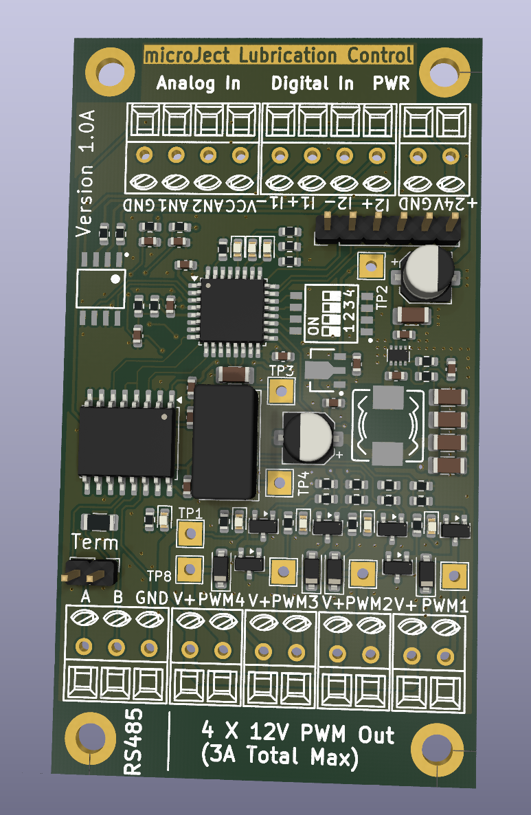
Control is via modbus RTU on RS485 or via switches and pots (Two channels only in that mode). Power input is 24V and power delivered to the injector heads is 12V at up to about 3A total from an on board power converter.
Firmware is written in Rust with Embassy as the framework and the processor on the board is an STM32F030k6.
#Electrical Interface
| Power supply | 24V @ 1.5A but usually much less. |
| Injector outputs | 12V @1A, 3A total max |
| Digital inputs | 2 Opto isolated, 24V max |
| Analogue inputs | 2, 3.3V max, intended for potentiometers |
| Serial interface | Isolated RS485 |
There is a 4 way dip switch on the board which configure the operating modes
| Switch | Function |
|---|---|
| 1 | Enables local control mode, the opto inputs and analog control the first two channels |
| 2 | Modbus alternate address, sets the modbus address to be 9 instead of 8 |
| 3, 4 | Modbus baud rate |
Baud rates
| SW 3 | SW 4 | Baud Rate |
|---|---|---|
| Off | Off | 4800 |
| Off | On | 9600 |
| On | Off | 19200 |
| On | On | 115200 |
Modbus interface is RTU over RS485 half duplex, formatted as 8-E-1.
Coils
| Coil | Description |
|---|---|
| 1 | Pulse enable for channel 1 |
| 2 | Pulse enable for channel 2 |
| 3 | Pulse enable for channel 3 |
| 4 | Pulse enable for channel 4 |
Note in modbus mode the coils will switch off 5 seconds after the last communication is received to avoid spilling coolant everywhere.
Holding Registers
| Register | Description |
|---|---|
| 1 | Channel 1 pulse length |
| 2 | Channel 1 period |
| 3 | Channel 2 pulse length |
| 4 | Channel 2 period |
| 5 | Channel 3 pulse length |
| 6 | Channel 3 period |
| 7 | Channel 4 pulse length |
| 8 | Channel 4 period |
Discrete inputs
| Input | Description |
|---|---|
| 1 | Enable input for ch1 when in local control mode |
| 2 | Enable input for ch2 when in local control mode |
Analogue inputs
| Input | Description |
|---|---|
| 1 | 0-3.3V period control input for channel 1 when in local control mode |
| 2 | 0-3.3V period control input for channel 2 when in local control mode |
Both the discrete inputs and the analogue channels can be read over modbus when not using local mode so you can readily use them for other things when using modbus for control.
When in local control mode (SW1 is on) the pulse length is defaulted to 1ms and the potentiometers control the pulse rate (1 - 1000Hz).
| Qty | Value | Footprint | References |
|---|---|---|---|
| 15 | 10k | Resistor_SMD:R_0603_1608Metric | R3, R4, R5, R6, R7, R8, R9, R10, R11, R12, R15, R16, R19, R22, R28 |
| 11 | 1uF | Capacitor_SMD:C_0603_1608Metric | C1, C2, C3, C4, C5, C6, C7, C8, C19, C20, C21 |
| 8 | LED | LED_SMD:LED_0603_1608Metric | D4, D5, D6, D7, D8, D9, D10, D14 |
| 8 | TestPoint | TestPoint:TestPoint_THTPad_2.5x2.5mm_Drill1.2mm | TP1, TP2, TP3, TP4, TP5, TP6, TP7, TP8 |
| 7 | 1k | Resistor_SMD:R_0603_1608Metric | R20, R21, R23, R29, R30, R31, R32 |
| 5 | Conn_01x02_Pin | PHOENIX THD:PHOENIX_1751099 | J7, J8, J9, J10, J12 |
| 4 | 10uF | Capacitor_SMD:C_1206_3216Metric | C29, C30, C31, C32 |
| 4 | AO3400A | Package_TO_SOT_SMD:SOT-23 | Q3, Q4, Q5, Q6 |
| 4 | B140HW-7 | Diode_SMD:D_SOD-123 | D11, D12, D13, D15 |
| 4 | MountingHole | MountingHole:MountingHole_3.2mm_M3_ISO14580_Pad | H1, H2, H3, H4 |
| 3 | 100nF | Capacitor_SMD:C_0603_1608Metric | C27, C28, C34 |
| 2 | 22uF 35V | Capacitor_SMD:CP_Elec_5x5.7 | C23, C25 |
| 2 | 4k7 | Resistor_SMD:R_0603_1608Metric | R17, R18 |
| 2 | Conn_01x04_Socket | PHOENIX THD:PHOENIX_1751112 | J3, J4 |
| 2 | NUP2105L | Package_TO_SOT_SMD:SOT-23 | D3, D16 |
| 1 | 10uF 50V | Capacitor_SMD:C_1206_3216Metric | C33 |
| 1 | 120R | Resistor_SMD:R_1206_3216Metric | R1 |
| 1 | 140k | Resistor_SMD:R_0603_1608Metric | R27 |
| 1 | 470pF 1kV | Capacitor_SMD:C_1206_3216Metric | C9 |
| 1 | 6.8uH | Inductors SMD:IND_MURATA-PS_4500 | L3 |
| 1 | ACPL-227-50BE | ICs And Semiconductors SMD:SOIC127P700X220-8N | IC4 |
| 1 | B2405S-1WR3 | Converter_DCDC:Converter_DCDC_Murata_CRE1xxxxxx3C_THT | U2 |
| 1 | Conn_01x02 | Connector_PinHeader_2.54mm:PinHeader_1x02_P2.54mm_Vertical | J2 |
| 1 | Conn_01x03_Socket | PHOENIX THD:PHOENIX_1751109 | J1 |
| 1 | HT7533-1(SOT89) | ICs And Semiconductors SMD:SOT89 | IC3 |
| 1 | ISO3082DW | Package_SO:SOIC-16W_7.5x10.3mm_P1.27mm | U4 |
| 1 | Programming header | Connector_PinHeader_2.54mm:PinHeader_1x06_P2.54mm_Vertical | J5 |
| 1 | STM32F030K6Tx | Package_QFP:LQFP-32_7x7mm_P0.8mm | U1 |
| 1 | Switch | Switches:SW_DIPTRONICS_DHA-04TQ | SW1 |
| 1 | TPS62933 | Package_TO_SOT_SMD:SOT-583-8 | U7 |
It measures 44.6 × 79.6 mm and has 2 copper layers, 1.6 mm thick.
96 parts, built around the B2405S-1WR3, ISO3082DW, TPS62933DRL and ACPL-227-50BE. The full list of its parts is on this page, with links to each part's symbol and footprint where PCBKit's library has them.
From the dan-mills/microJect repository on GitHub, at the commit this page was made from: the board is injector driver 2/injector driver 2.kicad_pcb and its schematic injector driver 2/injector driver 2.kicad_sch. PCBKit opens the board in the browser, with nothing to install.
Its repository publishes it under the Apache-2.0 licence: you may reuse it on that licence's terms (keep the author's notice, and for a copyleft licence share your changes alike).

tudsat-rocket/stigma
core board and mission board for a new flight computer

ElektorLabs/esp32-energymeter
The Elektor ESP32 Energy Meter project, featuring schematics, PCB designs, and ESPHome integration for advanced energy monitoring


