2 layers90 × 90 mm

 DADDesign-Projects/Asynchronous-SPDIF-Mixer13
"Asynchronous SPDIF Mixer" synchronizes and mixes up to three asynchronous S/PDIF streams into a 48 kHz output. Running on an STM32H743 and developed in C++ with CubeIDE, it compensates for drift with interpolation. A custom KiCad-designed PCB hosts this real-time audio processing solution.
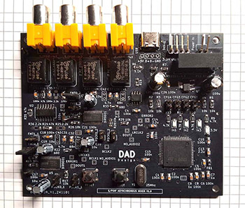
MIxer SPDIF V1.0 is an open-source printed circuit board by DADDesign-Projects, from the DADDesign-Projects/Asynchronous-SPDIF-Mixer repository on GitHub, published under the MIT licence. It is a 2-layer board of 100 × 84 mm with 141 parts on 167 nets, routed with 1,154 tracks and 75 vias.
It is built around the STM32H743VIT6, DIR9001PW and MAX3490ESA, with the 74HC04D, AMS1117-3.3 and PRTR5V0U2X among its other parts. Its parts include 44 capacitors, 38 resistors, 7 ICs, 7 connectors and 5 diodes. It belongs with the audio and music boards and the STM32 boards of this library.


"Asynchronous SPDIF Mixer" is a hardware and software project designed to synchronize and mix up to three asynchronous S/PDIF streams into a single 48 kHz output stream.
The system compensates for drift between sources and uses interpolation to ensure smooth and artifact-free audio transitions.
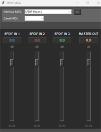
The project includes USB-MIDI control, allowing real-time mixing of the three audio channels via an external MIDI controller or any MIDI-compatible software.
The software, developed in C++ with CubeIDE, is optimized for real-time audio processing and runs on an STM32H743 microcontroller.
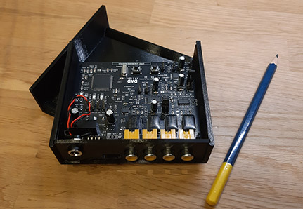
A custom electronic board, designed with KiCad, provides a dedicated hardware platform for this solution.
Recent updates to the project include:
This project is developed by DAD Design.
This project is licensed under the MIT License.
The KiCAD folder contains the schematics and PCB files for the project's hardware. These files were created using KiCAD version 9.0.
The project is developed and compiled using the CubeIDE environment provided by STMicroelectronics. CubeIDE is a fully integrated development environment (IDE) that supports STM32 microcontrollers and provides tools for debugging, flashing, and developing embedded systems.
| Qty | Value | Footprint | References |
|---|---|---|---|
| 24 | 100n | Capacitor_SMD:C_1206_3216Metric_Pad1.33x1.80mm_HandSolder | C1, C2, C3, C10, C11, C12, C15, C17, C18, C21, C22, C26, C27, C28, C33, C34 +8 |
| 12 | 10k | Resistor_SMD:R_1206_3216Metric_Pad1.30x1.75mm_HandSolder | R2, R3, R4, R5, R15, R16, R17, R18, R26, R27, R28, R29 |
| 6 | 75 | Resistor_SMD:R_1206_3216Metric_Pad1.30x1.75mm_HandSolder | R19, R20, R21, R23, R30, R34 |
| 4 | 10u | Capacitor_THT:CP_Radial_D5.0mm_P2.50mm | C16, C19, C20, C23 |
| 4 | 4.7K | Resistor_SMD:R_1206_3216Metric_Pad1.30x1.75mm_HandSolder | R9, R10, R12, R13 |
| 4 | 47k | Resistor_SMD:R_1206_3216Metric_Pad1.30x1.75mm_HandSolder | R8, R24, R31, R35 |
| 4 | PE 65612 | Local:PE-65612 | T1, T2, T3, T4 |
| 3 | 0 | Jumper:SolderJumper-2_P1.3mm_Bridged2Bar_Pad1.0x1.5mm | R1, R37, R38 |
| 3 | 2.2k | Resistor_SMD:R_1206_3216Metric_Pad1.30x1.75mm_HandSolder | R25, R32, R36 |
| 2 | 100u | Capacitor_THT:CP_Radial_D6.3mm_P2.50mm | C24, C25 |
| 2 | 15p | Capacitor_SMD:C_1206_3216Metric_Pad1.33x1.80mm_HandSolder | C29, C30 |
| 2 | 1u | Capacitor_SMD:C_1206_3216Metric_Pad1.33x1.80mm_HandSolder | C7, C9 |
| 2 | 2.2u | Capacitor_SMD:C_1206_3216Metric_Pad1.33x1.80mm_HandSolder | C13, C14 |
| 2 | 4.7k | Resistor_SMD:R_1206_3216Metric_Pad1.30x1.75mm_HandSolder | R11, R14 |
| 2 | 4.7n | Capacitor_THT:C_Rect_L4.6mm_W2.0mm_P2.50mm_MKS02_FKP02 | C42, C43 |
| 2 | 4.7n | Capacitor_SMD:C_1206_3216Metric_Pad1.33x1.80mm_HandSolder | C31, C37 |
| 2 | 5.1K | Resistor_SMD:R_1206_3216Metric_Pad1.30x1.75mm_HandSolder | R6, R7 |
| 2 | 680 | Resistor_SMD:R_1206_3216Metric_Pad1.30x1.75mm_HandSolder | R22, R33 |
| 2 | 68n | Capacitor_SMD:C_1206_3216Metric_Pad1.33x1.80mm_HandSolder | C32, C38 |
| 2 | 68n | Capacitor_THT:C_Rect_L4.6mm_W2.0mm_P2.50mm_MKS02_FKP02 | C41, C44 |
| 2 | DIR9001 | Local:TSSOP-28-1EP_4.4x9.7mm_P0.65mm_EP2.85x6.7mm | U5, U6 |
| 1 | 1K 100MHz | Capacitor_SMD:C_0805_2012Metric_Pad1.18x1.45mm_HandSolder | FB1 |
| 1 | 25Mhz | Local:Quartz | Y1 |
| 1 | 3.3V | LED_SMD:LED_1206_3216Metric_Pad1.42x1.75mm_HandSolder | D2 |
| 1 | 74HC04 | Package_SO:SO-14_5.3x10.2mm_P1.27mm | U2 |
| 1 | AMS1117-3.3 | Package_TO_SOT_SMD:SOT-223-3_TabPin2 | U7 |
| 1 | B1205_2W | Local:Converter_DCDC_TRACO_TBA1-xxxxE_Single_THT | PS1 |
| 1 | BCLK1 | TestPoint:TestPoint_THTPad_1.5x1.5mm_Drill0.7mm | TP1 |
| 1 | BCLK2 | TestPoint:TestPoint_THTPad_1.5x1.5mm_Drill0.7mm | TP8 |
| 1 | BOOT | Button_Switch_THT:SW_PUSH_6mm_H5mm | SW1 |
| 1 | CFG1 | Connector_PinHeader_2.54mm:PinHeader_1x02_P2.54mm_Vertical | JP1 |
| 1 | CFG2 | Connector_PinHeader_2.54mm:PinHeader_1x02_P2.54mm_Vertical | JP2 |
| 1 | CFG3 | Connector_PinHeader_2.54mm:PinHeader_1x02_P2.54mm_Vertical | JP3 |
| 1 | CFG4 | Connector_PinHeader_2.54mm:PinHeader_1x02_P2.54mm_Vertical | JP4 |
| 1 | DOUT1 | TestPoint:TestPoint_THTPad_1.5x1.5mm_Drill0.7mm | TP3 |
| 1 | DOUT2 | TestPoint:TestPoint_THTPad_1.5x1.5mm_Drill0.7mm | TP10 |
| 1 | Debug | Connector_PinHeader_2.54mm:PinHeader_1x04_P2.54mm_Horizontal | J2 |
| 1 | ERROR1 | TestPoint:TestPoint_THTPad_1.5x1.5mm_Drill0.7mm | TP4 |
| 1 | ERROR2 | TestPoint:TestPoint_THTPad_1.5x1.5mm_Drill0.7mm | TP11 |
| 1 | FMT0_1 | Connector_PinHeader_2.54mm:PinHeader_1x02_P2.54mm_Vertical | JP8 |
| 1 | FMT0_2 | Connector_PinHeader_2.54mm:PinHeader_1x02_P2.54mm_Vertical | JP12 |
| 1 | FMT1_1 | Connector_PinHeader_2.54mm:PinHeader_1x02_P2.54mm_Vertical | JP7 |
| 1 | FMT1_2 | Connector_PinHeader_2.54mm:PinHeader_1x02_P2.54mm_Vertical | JP11 |
| 1 | In1 | LED_SMD:LED_1206_3216Metric_Pad1.42x1.75mm_HandSolder | D5 |
| 1 | In1 | TestPoint:TestPoint_THTPad_1.5x1.5mm_Drill0.7mm | TP7 |
| 1 | In2 | LED_SMD:LED_1206_3216Metric_Pad1.42x1.75mm_HandSolder | D4 |
| 1 | In2 | TestPoint:TestPoint_THTPad_1.5x1.5mm_Drill0.7mm | TP13 |
| 1 | In3 | LED_SMD:LED_1206_3216Metric_Pad1.42x1.75mm_HandSolder | D3 |
| 1 | In3 | TestPoint:TestPoint_THTPad_1.5x1.5mm_Drill0.7mm | TP14 |
| 1 | LRCLK1 | TestPoint:TestPoint_THTPad_1.5x1.5mm_Drill0.7mm | TP2 |
| 1 | LRCLK2 | TestPoint:TestPoint_THTPad_1.5x1.5mm_Drill0.7mm | TP9 |
| 1 | MAX3490 | Package_SO:SOIC-8_3.9x4.9mm_P1.27mm | U3 |
| 1 | NO_AUDIO1 | TestPoint:TestPoint_THTPad_1.5x1.5mm_Drill0.7mm | TP5 |
| 1 | NO_AUDIO2 | TestPoint:TestPoint_THTPad_1.5x1.5mm_Drill0.7mm | TP12 |
| 1 | Out | TestPoint:TestPoint_THTPad_1.5x1.5mm_Drill0.7mm | TP6 |
| 1 | PRTR5V0U2X | Package_TO_SOT_SMD:SOT-143 | D1 |
| 1 | PSCK0_1 | Connector_PinHeader_2.54mm:PinHeader_1x02_P2.54mm_Vertical | JP6 |
| 1 | PSCK0_2 | Connector_PinHeader_2.54mm:PinHeader_1x02_P2.54mm_Vertical | JP10 |
| 1 | PSCK1_1 | Connector_PinHeader_2.54mm:PinHeader_1x02_P2.54mm_Vertical | JP5 |
| 1 | PSCK1_2 | Connector_PinHeader_2.54mm:PinHeader_1x02_P2.54mm_Vertical | JP9 |
| 1 | Power In | Connector_PinHeader_2.54mm:PinHeader_1x02_P2.54mm_Horizontal | J1 |
| 1 | RESET | Button_Switch_THT:SW_PUSH_6mm_H5mm | SW2 |
| 1 | S/PDIF-In1 | Local:CINCH_RCA | J5 |
| 1 | S/PDIF-In2 | Local:CINCH_RCA | J6 |
| 1 | S/PDIF-In3 | Local:CINCH_RCA | J7 |
| 1 | S/PDIF-Out | Local:CINCH_RCA | J4 |
| 1 | STM32H743VIT6 | Local:LQFP100-14x14mm | U1 |
| 1 | USB_C_Receptacle_USB2.0_16P | Connector_USB:USB_C_Receptacle_HCTL_HC-TYPE-C-16P-01A | J3 |
| 1 | W25Q64 | Package_SO:SOIC-8_5.23x5.23mm_P1.27mm | U4 |
The 136 most common of 141 parts.
It measures 100 × 84 mm and has 2 copper layers, 1.6 mm thick.
141 parts, built around the STM32H743VIT6, DIR9001PW, MAX3490ESA and 74HC04D. The full list of its parts is on this page, with links to each part's symbol and footprint where PCBKit's library has them.
From the DADDesign-Projects/Asynchronous-SPDIF-Mixer repository on GitHub, at the commit this page was made from: the board is KiCad/MIxer_SPDIF_V1.0.kicad_pcb and its schematic KiCad/Alims.kicad_sch. PCBKit opens the board in the browser, with nothing to install.
Its repository publishes it under the MIT licence: you may reuse it on that licence's terms (keep the author's notice, and for a copyleft licence share your changes alike).


Oleg-mk/MOST25-to-AUDIO
Passive MOST25 listener: Tang Nano 20K FPGA, ESP32 host, stereo I2S out with the head unit's volume, balance and tone


ajisrawi/atc-roip-gateway
Airborne Radio-over-IP (RoIP) gateway bridging aircraft VHF COM + HF transceivers to an IP network (Starlink) with an ED-137-style RTP/PTT/COR stream. KiCad hardware, routed 4-layer PCB, STM32H743 firmware.
