2 layers20 × 29.9 mm
Jst breakout
cyberboy666/lateral_led_controller
hardware network controller for addressable led installations
3 parts8GPL-3.0

 cyberboy666/lateral_led_controller8
hardware network controller for addressable led installations
Lateral led controller is an open-source printed circuit board by cyberboy666, from the cyberboy666/lateral_led_controller repository on GitHub, published under the GPL-3.0 licence. It is a 2-layer board of 100 × 60 mm with 30 parts on 46 nets, routed with 370 tracks and 14 vias.
It is built around the 74HC245D, WT32-ETH01 and RJ45. Its parts include 12 resistors, 7 connectors, 3 capacitors, 2 ICs and 2 diodes.


lateral_led_controller is a hardware interface that converts Art-Net, a network protocol for transmitting DMX data over network, into signals that drive addressable LEDs. it can be combined with mapping software (such as my artnet_led_mapper) to send arbitrary video onto an led strip canvas
features include:
8 parallel data outs and up to 12 DMX universes for max control over 2000 leds !this controller is a companion to my artnet_led_mapper application that converts a video feed into artnet for addressable led strip installations. it was built for lateral movement club nights such as seen here:
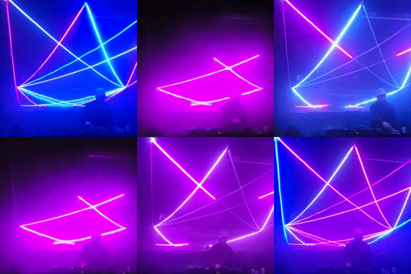
you can find some more background on this install and process here: WORKS IN PROGRESS 04 - talk about controlling addressable leds for art installation
besides this controller there are some more bits of hardware you will need to realize an addressable led installation - i will outline some suggestions here based on my experience but this will depend on your specific requirements - feel free to email me if you would like individual consulting on this.
this controller is configured to support two types of addressable led strips (more can be added by firmware update):
ie neopixels, WS2813 (5v) or WS2815 (12v)
we ended up using a switching power supply like this
for most installation settings it is prefered to use some kind of diffuser to help to evenly distribute light. there are many options and information about this topic online
the data lines from lateral_led_controller uses Pluggable Screw Terminals - standard wire (22awg etc) can connect these lines from controller to the strip
theres also the option to use cat5/6 cables to carry multiple data lines from the lateral_led_controller - these are quite cheap, come in long distances and have twisted pairs which should allow for longer runs
personally i prefer running power lines seperately (on red+black paired wire ) - and using these kinds of barrel / screw connectors to easily plug in / unplug from the installation
most led strips come with these SM JST 4 connectors pre-soldered to both ends. one option if you dont want to resolder wires / new connectors onto each strip would be to just get some extra of these and create breakouts
i made two little pcb adatpers that may help you with format convertion also - see below for some examples of how you could wire them
any software that can output artnet over a network can be used with lateral_led_controller. some programs i have tested it with include:
this project is fully open-source hardware - all the files required to build it are included in this repo for free. if you have the time and/or skill you can contribute back by collaborating on / testing new designs, improving these docs, making demo videos/other creative content etc. you can also support the project financially by donating directing, or purchasing through the web shop.
depending on whether you are going fully diy or buying an assembled and tested unit, some of the following guides will be relavent to you. the flow would be:
i try to source all the parts i can from either:
take a look at the full_bom for this project to see where i am sourcing each part from
go to the tayda quick order and in bottom corner choose add from file
select the file tayda_bom.csv in the BOM folder (you will have to download it first or clone this repo)
after importing select add to cart
NOTE: the minimum value for resistors is 10, so you may need to modify these values to add to cart (or if they are already modified here you will need to see the full_bom for actual part QTY)
OPTIONAL: it is a good idea to add some dip-ic sockets and 2.54pin headers/sockets to your tayda order if you dont have them around already
this circuit has a few specific parts that can not be sourced from tayda/mouser:
we are using a WT32-ETH01 ESP32 controller with the LAN8720A chip / ethernet port already attached - this is because it requires specific routing that is easier to get in a module like this - heres some more general info about this uC - it should be easy to find with a search on ali/amazon/ebay/etc - if you get it without header pins you can solder the controller straight on to the pcb (using the castellated edges)
another pre-soldered module used in this circuit is this MP1584EN_5v_stepdown - 3A Step-down 5v
its a useful module that allows a wide range of voltage inputs and is much more efficent than standard linear regulators (so producing less heat - which is important for installation work) - you can also solder the board directly onto our pcb with the castellated edges - take note of the direction indicated by arrow on bottom of module
since the WT32-ETH01 doesnt have an on-board usb-to-serial on the module for uploading firmware this board is designed to work with this WeMos_CH340G_USB_to_SERIAL one - we are using this because it outputs the command signals that allow for auto-uploading (so we dont need to manually switch to boot mode every time) - you may need to join some pads with solder on the module to select DTS mode for it to work
the footprints on the pcb for the data line outputs are spaced for 3.5MM
you can support this project by buying individual pcbs from the shop. if you would rather have pcbs fabricated from gerbers directly the file you need is here
add gerber file buttoni often use jlcpcb because they are reliable, cheap and give you an option of colours. remember though that the cheapest Chinese fab houses are not always the most ethical or environmently friendly - if you can afford it consider supporting local companies.
follow this link to view the interactive BOM
remember to heat pad first (2-3seconds), then add solder, then continue to heat (1-2seconds)
Checkout the web-comic soldering is easy for more soldering advice
both the WT32-ETH01 controller and the MP1584EN_5v_stepdown module can be soldered directly to the board using the castellated edges (if you would rather use pins/sockets this is fine also - just be aware you may need to use higher standoffs if also mounting a front panel) - these should be soldered before anything else
next i would solder the resistors, capictors (take note of direction), diodes, transistors etc
finally would finish with ic's and interface parts - sockets, buttons etc...
if you have got a kit from the shop the default firmware will be pre-configured - still it could be useful to know how to update firmware / customize your controller.
all underscores projects with micro-controllers use platformio with visual studio code to edit, flash and monitor the code.
platformio to install this extension
PlatformIO: Upload should flash the default code to your micro-controller
leds pw ledsleds - you should see the blue network connected led come on when you have connected to this networkhttp://leds.local (also try http://192.168.4.1 if that doesnt work ) - you should now see the web interface!on the controller board next to the NETWORK CONNECTED led is a CONTROLLER RESET button - pushing this will reboot the controller -> you should see the network connected light go off for a momement while it resets
if you hold down the CONTROLLER RESET button for 5 seconds then release it you should see the NETWORK CONNECTED led flashing -> then short pressing the CONTROLLER RESET again from this mode will perform a hard reset this means that the NETWORK TYPE is reset back to ACCESS_POINT and all settings are restored to default (you will need to connect to leds with pw ledsleds again to set up your controller)
this can be helpful if you accidently put the controller into a state with network settings that you can not access the page any more.
(if you get to the flashing led state but do not want to do a hard reset just power down the controller while flashing and your settings will not be wiped)
[coming soon]
if you would like to contribute back to these projects in some way but dont know how the best thing (for now) would be to reach out to me directly ( tim@cyberboy666.com or @cyberboy666 on scanlines forum) - i will be happy to help
This circuit is distributed through UNDERSCORES – open video hardware label – visit underscores.shop for more info
The pcb was designed using KICAD , the booklet was created in LibreOffice Draw
Everything from gerbers, cad files, panels and documentation is freely available online and distributed under CC-BY-SA / open-source licenses – help us contribute to the commons !
Ask any questions or start discussions related to this project on the scanlines.xyz forum – an online community space dedicated to diy av / electronic media art
You can contact me directly at tim (at) cyberboy666 (dot) com Please get in touch if you are interested in hosting a workshop !
thanks to Tor for user testing + detailed feedback and suggestions + help with web interface design. thanks to the Lateral Movement Crew: Leo, Teesh, Wendy, Luke, Sean - for all the work into making these parties happen
| Qty | Value | Footprint | References |
|---|---|---|---|
| 9 | 100 | Resistor_THT:R_Axial_DIN0204_L3.6mm_D1.6mm_P5.08mm_Horizontal | R3, R4, R5, R6, R7, R8, R9, R10, R11 |
| 3 | 10k | Resistor_THT:R_Axial_DIN0204_L3.6mm_D1.6mm_P5.08mm_Horizontal | R1, R2, R12 |
| 2 | 2N3904 | Package_TO_SOT_THT:TO-92_HandSolder | Q1, Q2 |
| 2 | RJ45 | lib_fp:RJ45_Horizontal | J2, J3 |
| 2 | terminal_04 | TerminalBlock_Phoenix:TerminalBlock_Phoenix_PT-1,5-4-3.5-H_1x04_P3.50mm_Horizontal | J4, J5 |
| 1 | 0.1u | Capacitor_THT:C_Disc_D6.0mm_W2.5mm_P5.00mm | C3 |
| 1 | 10u | Capacitor_THT:CP_Radial_D5.0mm_P2.00mm | C1 |
| 1 | 1n5819 | Diode_THT:D_DO-34_SOD68_P7.62mm_Horizontal | D2 |
| 1 | 220u | Capacitor_THT:CP_Radial_D5.0mm_P2.00mm | C2 |
| 1 | 74HC245 | Package_DIP:DIP-20_W7.62mm_LongPads | U2 |
| 1 | Barrel_Jack_Switch | Connector_BarrelJack:BarrelJack_Horizontal | J6 |
| 1 | LED | LED_THT:LED_D5.0mm | D1 |
| 1 | MP1584EN_5v_stepdown | lib_fp:MP1584EN_stepdown_module | J8 |
| 1 | Polyfuse | Fuse:Fuse_Bourns_MF-RG300 | F1 |
| 1 | SW_Push | Button_Switch_THT:SW_Tactile_SKHH_Angled | SW1 |
| 1 | WT32-ETH01 | lib_fp:WT32-ETH01 | U1 |
| 1 | WeMos_CH340G_USB_to_SERIAL | Connector_PinHeader_2.54mm:PinHeader_1x06_P2.54mm_Horizontal | J1 |
It measures 100 × 60 mm and has 2 copper layers, 1.6 mm thick.
30 parts, built around the 74HC245D, WT32-ETH01 and RJ45. The full list of its parts is on this page, with links to each part's symbol and footprint where PCBKit's library has them.
From the cyberboy666/lateral_led_controller repository on GitHub, at the commit this page was made from: the board is hardware/lateral_led_controller.kicad_pcb and its schematic adapter/jst_breakout/jst_breakout.kicad_sch. PCBKit opens the board in the browser, with nothing to install.
Its repository publishes it under the GPL-3.0 licence: you may reuse it on that licence's terms (keep the author's notice, and for a copyleft licence share your changes alike).
cyberboy666/lateral_led_controller
hardware network controller for addressable led installations

cyberboy666/lateral_led_controller
hardware network controller for addressable led installations


MetaMakersCooperative/M2C_Yet_Another_Door_Controller
Proof of concept for new door controller design using a WT32-ETH01.


loack/ESP32-ETH01-WifiMQTT-Controller
Contrôleur générique d'I/O pour WT32-ETH01 avec Ethernet prioritaire et fallback WiFi.

LuisMiguel-efe/unikey
Sistema inteligente de control de acceso universitario mediante huella dactilar, con autenticación biométrica, FastAPI, MongoDB y Angular.

ondras12345/CNC
My CNC 1610 and Stepcraft model 600 configuration and CNC-related notes

sensslen/Cfg.CameraControl.Hardware
Hardware needed to control a lanc camera with a PTZ head