
6 layers159.3 × 60.8 mm
Combolite2
ekundo/combolite
ComboLite: плата расширения для «Вектора-06Ц» — квазидиски, IDE, дисковод, AY, VGA, Wi-Fi
187 parts2GPL-3.0

BLE smart ring main board — 2-layer rigid-flex KiCad PCB (nRF52832 + LSM6DSV16X IMU/Qvar). PCB layout, schematic, footprints.
Ring is an open-source printed circuit board by Curtisflo, from the Curtisflo/swipe-smart-ring repository on GitHub, published under the MIT licence. It is a 2-layer board of 38 × 10 mm with 30 parts on 19 nets, routed with 322 tracks and 78 vias.
It is built around the ANNA-B112-02B, LSM6DSV16X and ESDALCL5-1BM2, with the BAT54W-E3-08 and IRLML6344TRPBF among its other parts. Its parts include 8 resistors, 4 capacitors, 3 diodes, 2 ICs and 2 connectors. It belongs with the radio and wireless and sensors and measurement boards of this library.


The main board for a BLE smart ring with IMU-based gesture input and capacitive touch. This repo contains the ring board KiCad project: PCB layout, schematic, and the custom footprints used by both.
Status: prototype, not yet fabricated or tested. Routed and verified in KiCad 9 — DRC clean: 0 errors, 0 warnings, 0 unconnected nets.
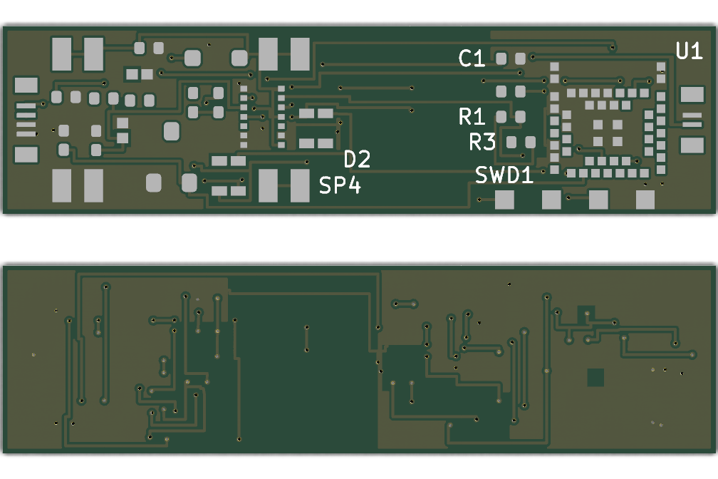
It's small — the board outline is 38 × 10 mm (about the footprint of a stick of gum).
The board isn't meant to stay flat. The middle 8 mm is a flex section: the rigid signet and BLE ends fold relative to each other there, so the board follows the curve of the finger inside the housing. In the housing the BLE end sits 115° around the ring from the signet, and the rigid ends stay flat — so the 8 mm flex takes that whole ~115° bend (about a 4 mm radius, well inside the material's 0.6 mm minimum).
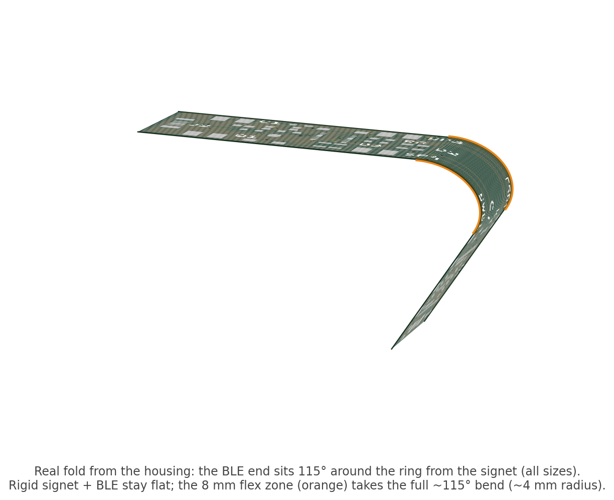
A note on the rigid-flex: the flex zone is captured here as design intent —
the layout is zoned signet (18 mm) / flex (8 mm) / BLE (12 mm) along the board's
length, with the bend taken by the middle 8 mm. The ring.kicad_pcb itself is a
flat 2-layer prototype; the actual rigid-flex stackup and coverlay callouts are
left to the fabricator.
A 2-layer rigid-flex board that wraps around a finger. It carries a Nordic nRF52832 BLE SoC, a 6-axis IMU with built-in capacitive (Qvar) touch sensing, a haptic motor driver, indicator LEDs, and the spring contacts / connectors that mate with the ring housing.
The board is split into three zones along its length:
[ signet  18mm rigid ] —— [ flex 8mm ] —— [ BLE 12mm rigid ]
  battery + motor +                          ANNA-B112 module +
LED arc + drivers antenna keepout + SWD| Ref | Part | Function |
|---|---|---|
| U1 | u-blox ANNA-B112 (nRF52832) | BLE SoC module, pre-certified, integrated antenna |
| U2 | ST LSM6DSV16X | 6-axis IMU + Qvar capacitive touch, LGA-14 |
| Q1 | Infineon IRLML6344 | N-ch MOSFET, haptic motor low-side drive |
| D1 | Vishay BAT54W | Schottky motor flyback clamp |
| D2, D3 | American Bright BL-HG0E136J | Bicolor indicator LEDs |
| ESD1/2 | ST ESDALCL5-1BM2 | ESD protection on the Qvar electrode lines |
| J1 | Molex 5034800240 | 2-pin FPC — pogo/charge harness (VBUS, GND) |
| J2 | Molex 5034800440 | 4-pin FPC — electrode harness (Qvar×2, GND×2) |
| SP1–SP4 | KYOCERA AVX 70-9155 | Spring contacts — battery (×2) and motor (×2) |
Full line-item list (passives, MPNs, prices) in bom.csv. The
battery (Seiko MS920SE coin cell) and haptic motor are off-board — they sit in
the housing and contact the spring pads — and are listed at the end of the BOM.
The full product also includes a pogo charge-contact board, a Qvar electrode flex, and a USB-C dock — those are not part of this repo.
Built with KiCad 9. Clone and open ring.kicad_pro, or open
ring.kicad_pcb / ring.kicad_sch directly. Footprints are embedded in the
board, and the custom.pretty library is included for editing.
ring.kicad_pcb — routed PCB layoutring.kicad_sch — schematicring.kicad_pro — KiCad projectcustom.pretty/ — custom footprintsbom.csv — bill of materials for this boardring-schematic.pdf — schematic as a PDF (no KiCad needed)preview.png — rendered board, top and bottom (KiCad 9, 38 × 10 mm)preview-3d.png — 3D view of the rigid-flex fold at the flex zonefab/ — Gerbers and Excellon drill files (KiCad 9 export), ready to orderMIT — see LICENSE.
| Qty | Value | Footprint | References |
|---|---|---|---|
| 4 | 709155001610004 | AVX_9155_Battery_Contact | SP1, SP2, SP3, SP4 |
| 2 | 100nF | R_0402_1005Metric | C1, C2 |
| 2 | 10k | R_0402_1005Metric | R1, R2 |
| 2 | 110pF | R_0402_1005Metric | C7, C8 |
| 2 | 500R | R_0402_1005Metric | R4, R5 |
| 2 | BL-HG0E136J-TRB | LED_0605_BiColor | D2, D3 |
| 2 | ESDALCL5-1BM2 | D_SOD-882 | ESD1, ESD2 |
| 1 | 100R | R_0402_1005Metric | R6 |
| 1 | 100k | R_0402_1005Metric | R8 |
| 1 | 2.2k | R_0402_1005Metric | R3 |
| 1 | 5034800240 | Molex_503480_2pin | J1 |
| 1 | 5034800440 | Molex_503480_4pin | J2 |
| 1 | 82R | R_0402_1005Metric | R7 |
| 1 | ANNA-B112-02B | ANNA-B112 | U1 |
| 1 | BAT54W-E3-08 | D_SOD-123 | D1 |
| 1 | IRLML6344TRPBF | SOT-23 | Q1 |
| 1 | LSM6DSV16X | LGA-14_2.5x3mm_P0.5mm_LSM6DSV16X | U2 |
| 1 | SWD1 | Pad_1.0x1.0mm | SWD1 |
| 1 | SWD2 | Pad_1.0x1.0mm | SWD2 |
| 1 | SWD3 | Pad_1.0x1.0mm | SWD3 |
| 1 | SWD4 | Pad_1.0x1.0mm | SWD4 |
ekundo/combolite
ComboLite: плата расширения для «Вектора-06Ц» — квазидиски, IDE, дисковод, AY, VGA, Wi-Fi

Protocentral/protocentral_st1vafe3bx_hardware
KiCad hardware design files for the ProtoCentral ST1VAFE3BX biopotential AFE + 3-axis accelerometer breakout (CERN-OHL-P v2).

dahan8473/tethos-port
A tiny CRT-TV virtual pet keychain with BLE. Tethos / Tech for Social Impact merch. PCB + case as code.

jayis1/hardware-design-lab
Full-cycle hardware device designs — each device in its own subfolder with architecture, schematics, PCB layout, and software stack


GeneralSyb/Sagittarius-Headtracker
Project files for the Sagittarius S1 Prototype


It measures 38 × 10 mm and has 2 copper layers, 0.1 mm thick.
30 parts, built around the ANNA-B112-02B, LSM6DSV16X, ESDALCL5-1BM2 and BAT54W-E3-08. The full list of its parts is on this page, with links to each part's symbol and footprint where PCBKit's library has them.
From the Curtisflo/swipe-smart-ring repository on GitHub, at the commit this page was made from: the board is ring.kicad_pcb and its schematic ring.kicad_sch. PCBKit opens the board in the browser, with nothing to install.
Its repository publishes it under the MIT licence: you may reuse it on that licence's terms (keep the author's notice, and for a copyleft licence share your changes alike).