
2 layers80 × 110 mm
NucDeck Left Controller PCB
dmcke5/NucDeck
The Open Source DIY Handheld Gaming PC!
59 parts561CERN-OHL-S-2.0
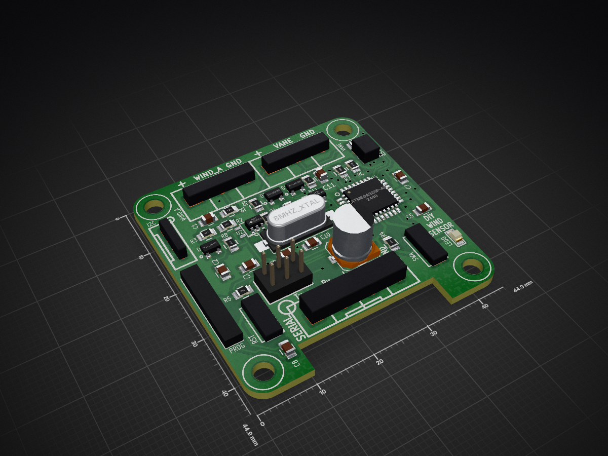
 curiouselectric/WindSensor2
A DIY interface circuit for anemometers and wind vanes
WindSensorATMEGA328 PCB is an open-source printed circuit board by curiouselectric, from the curiouselectric/WindSensor repository on GitHub. It is a 2-layer board of 44.9 × 44.9 mm with 42 parts on 37 nets, routed with 470 tracks and 34 vias.
It is built around the ATMEGA328P-AU. Its parts include 12 resistors, 11 capacitors, 9 connectors, 4 diodes and 3 ICs. It belongs with the interfaces and adapters boards and the AVR (ATmega, ATtiny) boards of this library.
A DIY Wind sensor interface board.
This connects to various anemometers and wind vanes and provides a serial interface for averaged data from the pulses.
The problem with measuring wind anemometers and wind vane is that they constantly need to be checked. You need to know at all times when pulses have come in and which direction the wind vane is facing. This requires a bit of microcontroller time and processing. This unit is designed to solve that. Wire up your vane and anemometer. Power the unit up. Then it will save the averaged data for you. You can then get hold of the data through serial requests and process as you need.

I wrote this to interface to an ESP32 data logger, which sleeps most of the time. It wakes up, talks to the wind sensor, gets the data it needs, then goes back to sleep, knowing the wind sensor is always monitoring.
It was designed as a relatively simple interface to remove the need for monitoring pulses and averaging them.
The anemometer can either be a pulse output, NPN output or hall-effect output. The unit reads digital pulses, with circuitry on the unit converting the hall effect output to pulses. (Note: This unit cannot read 0-5V or analog output sensors).
The unit stores average wind speeds for 1 second, 10 second, 1 min, 10 min and 1 hour values. It also records the maximum and minimum wind speed.
The unit converts the pulses into a real wind speed using a y=mx+c linear conversion, where y is the wind speed and c is the number of pulses. m and c are stored in EEPROM and have default values of m=1 and c=0. These are floats and can be changed as required through the serial interface. Any updated values are stored in EEPROM. If the pulses are zero then the output is also zero (no matter what the y=mc+c function is). This stops a reading of 'c' when the pulse data is zero.
The wind vane input is analog.
This can read either resistive wiper vanes or stepped resistive vanes.
The stepped rsistive vanes have magnet reed switches which switch in and out different resistances. The resistance then tells us the direction. A pull up reistor is required in these situations.
The wind vane input can be 'trained'. So put the unit into vane training mode via the serial interface. This will run through N, NE, E, SE, S, SW, W, NW and you can hold the unit in the correct direction position and press the switch to store that data to memory. Once trained then the unit creates a buffer zone around each of the values and within the zone then the unit will record the correct direction.
Wind direction is slightly difficult to measure, as you cannot directly average the analog value (because of the potential rollover point from 360 degrees to 0 degrees point where the analog pin value rolls around from 1024 back to 0 - this means an average of a unit pointing just off north (i.e. one reading of 0 and one reading of 360) will give an average of (360+0)/2 = 180, which is south and totally wrong!). The code here creates 'bands', along with a 'rollover' band so that (for example) 900 to 1024 and 0 to 36 will be linked to North, so that the roll over point is handled as best as possible.
This unit will record the number of seconds the vane has been pointing in a certain direction. This means a 'wind rose' can relatively easily be created. This is stored and updated until it is directly reset. The unit will also return the instantaneous direction, if that is needed.
There are two mode of operation, depending upon your use case (please see the firmware for more detailled information about the available serial commands):
In this mode then the unit responds to serial requests made. You ask the sensor for data and this is returned. It never sends anything unless asked.

In this mode then the unit regularly sends data via the serial connunication. It will send the averaged data for (0) 1 second, (1) 10 second, (2) 1 min, (3) 10 min and (4) 1 hour averaged data. If this is set to (5) then the unit does not send any data. The send mdoe is stored in EEPROM, so it will start sending data again even if power is lost.

Boradcast mode works well if the logger is always listening and you only have one sensor in range. If more than one sensor is in range then the data will clash and potentially cause issues, in which case use Response mode.
The two modes work together - you can have the unit sending regular data and also responding to requests.
It runs on an ATMega328 running at 8MHz (external crystal) with selectable baud serial (up to 57600). It comes pre-programmed, but code can be uploaded via the Arduino IDE, using the MiniCore board add-on. See firmware for more details.
The PCB was designed in KiCAD and is available here. A small PCB has been designed. There is one reset switch, one user input switch and one LED output.
Both inputs for the wind vane and anemometer are buffered with an op-amp and also have 5.1V zener protection. The anemometer input compares the input with a low voltage level to create a pulse from a hall-effect (which output a sine-wave like signal). This also works as a pull-down pulse sensor, which works with NPN and switch output anemometers.
| Anemometer Name | Link | Type | m Value | c Value |
|---|---|---|---|---|
| Vector Insrutments NRG #40C | https://www.nrgsystems.com/products/met-sensors/detail/40c-anemometer | Hall-effect | 0.765 for m/s | 0.35 for m/s |
| Maplin Anemometer (low cost) | https://www.ebay.co.uk/itm/274338314354 | Reed-switch pulse | 0.7 for m/s | 0 for m/s |
| Curios Electric PR-3000-FS-NPN | https://www.curiouselectric.co.uk/collections/featured/products/anemometer-for-wind-speed-measurements | NPN Pulse | 0.0875 for m/s | 0 for m/s |
| Pro-D Anemometer/Vane combination | https://cdn.shopify.com/s/files/1/0115/9192/files/Pro-D_Anemometer_Specs_v2.docx.pdf | Magnetic pulse | 1.006 for m/s | 0 for m/s |
| Wind Vane Name | Link | Type |
|---|---|---|
| Maplin Vane | No Link | Switched resistive |
| Pro-D Anemometer/Vane combination | https://cdn.shopify.com/s/files/1/0115/9192/files/Pro-D_Anemometer_Specs_v2.docx.pdf | 20k resistive |
| Curios Electric ZTS-3000-TR-FSJT-NPN | https://www.curiouselectric.co.uk/collections/featured/products/wind-vane-for-wind-direction-measurements | 0-3.3V output |
Each unit can have a unique ID (using a solder pad for 0-7 values), so multiple units can be added to a serial bus, if needed. The defalt is 0.
This uses an ATMega328 running at 8MHz with 3.3v or 5V supply.
The firmware used in this project is available in this github repository:
https://github.com/curiouselectric/SensorInterfaceFirmware
Please follow the information within that repository for the serial commands and firmware information.

| Qty | Value | Footprint | References |
|---|---|---|---|
| 7 | 100n | REInnovationFootprint:SM_C_0805 | C1, C3, C4, C5, C7, C8, C11 |
| 5 | 10k | REInnovationFootprint:SM0805 | R1, R5, R10, R11, R12 |
| 4 | 4k7 | REInnovationFootprint:SM0805 | R2, R3, R6, R7 |
| 2 | 22p | REInnovationFootprint:SM_C_0805 | C9, C10 |
| 2 | 3V3_Zener | REInnovationFootprint:SOT23_ZENER | D1, D4 |
| 2 | TSV911xxLx | REInnovationFootprint:SM_SOT-23-5 | U1, U2 |
| 1 | 100k | REInnovationFootprint:SM0805 | R9 |
| 1 | 100u | REInnovationFootprint:SM_6.3x7.7 | C6 |
| 1 | 22n | REInnovationFootprint:SM_C_0805 | C2 |
| 1 | 470 | REInnovationFootprint:SM0805 | R4 |
| 1 | 470k | REInnovationFootprint:SM0805 | R8 |
| 1 | 5V1_Zener | REInnovationFootprint:SOT23_ZENER | D3 |
| 1 | 8MHz_XTAL | REInnovationFootprint:SM-crystal-HC49UP | Y1 |
| 1 | ATmega328P-AU | REInnovationFootprint:TQFP32-08 | U4 |
| 1 | I2C | REInnovationFootprint:SIL-4_Grove_Not_Labelled | P10 |
| 1 | ID | REInnovationFootprint:SM_6pad_3W_SOLDER | P3 |
| 1 | ISP | REInnovationFootprint:ISP_3x2 | P4 |
| 1 | LED0 | REInnovationFootprint:SM0805_LED | D2 |
| 1 | LOGO2 | CuriousElectric3:TCEC_Words_13mm | P5 |
| 1 | PCB | REInnovationFootprint:PCB_45_45_Cut_Out_Solar_Sensor_2 | P6 |
| 1 | PROG | REInnovationFootprint:TH_6x1_FTDI | P9 |
| 1 | RST | REInnovationFootprint:SMD_SW_6x3_5 | SW2 |
| 1 | SERIAL | REInnovationFootprint:SIL-4_Grove_SCREW | P2 |
| 1 | SWA | REInnovationFootprint:SMD_SW_6x3_5 | SW1 |
| 1 | VANE | REInnovationFootprint:SIL-3_screw_terminal | P8 |
| 1 | WIND_A | REInnovationFootprint:SIL-3_screw_terminal | P11 |
It measures 44.9 × 44.9 mm and has 2 copper layers, 1.6 mm thick.
42 parts, built around the ATMEGA328P-AU. The full list of its parts is on this page, with links to each part's symbol and footprint where PCBKit's library has them.
From the curiouselectric/WindSensor repository on GitHub, at the commit this page was made from: the board is Wind Sensor PCB/WindSensorATMEGA328_PCB.kicad_pcb and its schematic Wind Sensor PCB/Hall_to_Freq.kicad_sch. PCBKit opens the board in the browser, with nothing to install.
Its repository states no licence, so its author keeps all rights: ask curiouselectric before reusing the design.
dmcke5/NucDeck
The Open Source DIY Handheld Gaming PC!


profdc9/RFBitBanger
A QRP digital transceiver created from readily available parts for off-the-grid maintenance

futureshocked/KLP4e_MCU-Datalogger
This is the repository for the "MCU Datalogger" project.


sportiduino/sportiduino
Electronic timing system for orienteering and similar outdoor sports events on Arduino

SukkoPera/OpenPSX2AmigaPadAdapter
Playstation to Commodore Amiga/CD32 Controller Adapter

4x1md/vx8_gps
DIY GPS module for Yaesu VX-8DR/VX-8DE handheld transceiver.