2 layers100 × 55 mm
WellD
kinggh0stee/WellD
ESP32-C6 Zigbee well monitor — reads a 4–20 mA pressure transducer and DS18B20, reports water level, temperature, and battery to Zigbee2MQTT with OTA update support
122 parts2MIT

 cristi-zz/ha-pcb
PCB for my home automation. For reviewing purposes.
Ha pcb is an open-source printed circuit board by cristi-zz, from the cristi-zz/ha-pcb repository on GitHub. It is a 2-layer board of 137.2 × 111.8 mm with 55 parts on 82 nets, routed with 463 tracks and 1 via.
It is built around the DS18B20, PCF8575DB and ADS1115. Its parts include 17 connectors, 13 resistors, 11 ICs, 5 diodes and 4 capacitors.


The story behind this, can be found on my blog
It will hold a series of breakout boards for I2C IO expanders, 1Wire drivers, ADCs. All are controlled with a Raspberry Pi 3B+.
The 220V actuators are controlled by a board with 16 mechanical relays. The board is in turn controlled by PCF8575 chip that takes I2C commands and controls 16 I/O pins. Board is active on low (optocouplers), PCF8575 can sink more current (than it could source). Perfect match.
The 16 relay board is separate, from this PCB, only a pin header connection is made.
The temperature sensors are DS18B20 that work on 1 wire protocol. These are already mounted with Ethernet cables terminated with RJ45. The sensors are read/driven by 4 ds2482s-100 chips (RJ45 terminals and ds2482s-100 are on this PCB). The RJ jacks must be galvanic!
There are some other relays/contactors/voltages that needs monitoring, all done by 2 ADS1115 16-Bit ADC, present on board.
The chips are already sourced and live on their breakout boards. The PCB is mainly THT because of sourcing issues (eg can't find ds2482s-100 anywhere, will reuse existing breakouts). Only SMD are the 3.5 audio jacks (for ADC) again because no THT could be sourced atm.
The Raspberry Pi connector is only 20 pin wide because only the first few are used (5V, 3.3, SDA, SCL, GND)
There is a spurious bug, all relays are ON when the 16 relay board is powered but the Raspberry (that powers the rest of the circuits) is OFF. So, a solid state relay is used to cut power to the relay board when the RaPi is shutted down.
With the exception of ADCs, the schema and design choices follow the existing (4 years old) system.
This repo is mainly for reviewing purposes.
The story behind this PCB is on www.visoft.ro

A list with the devices
https://www.sainsmart.com/products/16-channel-12v-relay-module
https://www.artekit.eu/products/breakout-boards/io/ak-pcf8575-i2c-16-bit-io-expander-breakout/
https://www.pololu.com/product/2595
https://www.sparkfun.com/products/retired/14589
https://www.artekit.eu/products/breakout-boards/io/ak-ds2482s-100/
https://www.adafruit.com/product/1085
Some ADC "watch" only for presence/absence of 5V power but some are listenting to CT sensors. Quasi similar model: https://www.seeedstudio.com/Non-invasive-AC-Current-Sensor-30A-ma-p-519.html
https://www.tme.eu/en/details/dmo063/dc-solid-state-relays/crydom/
Add comments here (as git issues) or on EEVBlog.
| Qty | Value | Footprint | References |
|---|---|---|---|
| 5 | 1K | Resistor_THT:R_Axial_DIN0207_L6.3mm_D2.5mm_P10.16mm_Horizontal | R1, R10, R11, R12, R13 |
| 5 | 3.5Inch_Audio | Library:3.5mmJack SMD | J12, J13, J14, J15, J16 |
| 4 | 10K | Resistor_THT:R_Axial_DIN0207_L6.3mm_D2.5mm_P10.16mm_Horizontal | R2, R3, R4, R5 |
| 4 | AK-DS2482S-100 | Library:AK-DS2482S-100 | U4, U7, U10, U11 |
| 4 | MountingHole | MountingHole:MountingHole_2.5mm | H1, H2, H3, H4 |
| 3 | 47K | Resistor_THT:R_Axial_DIN0207_L6.3mm_D2.5mm_P10.16mm_Horizontal | R6, R7, R9 |
| 3 | LED | LED_THT:LED_D5.0mm | D1, D4, D5 |
| 3 | RJ45_1W1W | Library:RJ45_Ninigi_GE_silver | J8, J10, J11 |
| 2 | 1N4001 | Diode_THT:D_DO-41_SOD81_P10.16mm_Horizontal | D2, D3 |
| 2 | 4.7uF | Capacitor_THT:CP_Radial_D4.0mm_P2.00mm | C1, C2 |
| 2 | ADS1115 | Library:ADS1115 | U8, U9 |
| 2 | RJ45_NC1W | Library:RJ45_Ninigi_GE_silver | J1, J5 |
| 1 | 0.1uF | Capacitor_THT:CP_Radial_D4.0mm_P2.00mm | C3 |
| 1 | 12V IN | TerminalBlock_RND:TerminalBlock_RND_205-00001_1x02_P5.00mm_Horizontal | J2 |
| 1 | 12V OUT | TerminalBlock_RND:TerminalBlock_RND_205-00001_1x02_P5.00mm_Horizontal | J3 |
| 1 | 4.7K | Resistor_THT:R_Axial_DIN0207_L6.3mm_D2.5mm_P10.16mm_Horizontal | R8 |
| 1 | 470uF/16V | Capacitor_THT:CP_Radial_D8.0mm_P3.80mm | C4 |
| 1 | Conn_01x05 | Connector_PinHeader_2.54mm:PinHeader_1x05_P2.54mm_Vertical | J6 |
| 1 | DMO063_SSR | Library:DMO063_SSR | U1 |
| 1 | DS18B20 | Package_TO_SOT_THT:TO-92_Inline_Wide | U6 |
| 1 | Jumper_2_Open | Connector_PinHeader_2.54mm:PinHeader_1x02_P2.54mm_Vertical | JP1 |
| 1 | PCA9615_I2C_Diff | Connector_PinHeader_2.54mm:PinHeader_1x05_P2.54mm_Vertical | U5 |
| 1 | PCF_8575 | Library:PCF_8575 | U3 |
| 1 | Pololu_Level_Shifter | Library:Pololu Level Shifter | U2 |
| 1 | RaPi_Connector | Connector_PinHeader_2.54mm:PinHeader_2x10_P2.54mm_Vertical | J4 |
| 1 | SainSmart_connector | Connector_PinHeader_2.54mm:PinHeader_2x10_P2.54mm_Vertical | J7 |
| 1 | locked | Library:RJ45_Ninigi_GE_silver | J9 |
| 1 | locked | Library:3.5mmJack SMD | J17 |
kinggh0stee/WellD
ESP32-C6 Zigbee well monitor — reads a 4–20 mA pressure transducer and DS18B20, reports water level, temperature, and battery to Zigbee2MQTT with OTA update support

heliumonoxide/water_quality_monitoring_device
Water Quality Monitoring in Water Fountain at Gedung K Faculty of Engineering UI

ka1e27/dreams
Autonomous survey catamaran: CV-based obstacle avoidance, environmental sensing, and cellular telemetry to a web dashboard.

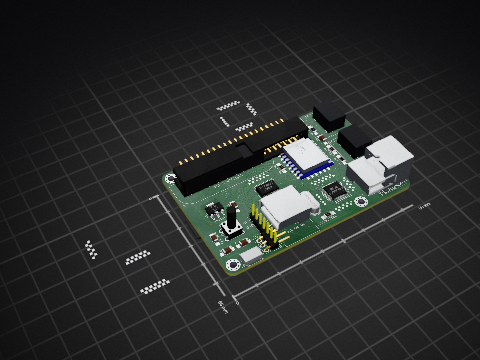
uli/basicengine-pcb
Schematics and PCB layout for the BASIC Engine home computer


jkordek1/Man-Don-t-Get-Angry-Board-game
"Man don't get mad" - electronic board game

It measures 137.2 × 111.8 mm and has 2 copper layers, 1.6 mm thick.
55 parts, built around the DS18B20, PCF8575DB and ADS1115. The full list of its parts is on this page, with links to each part's symbol and footprint where PCBKit's library has them.
From the cristi-zz/ha-pcb repository on GitHub, at the commit this page was made from: the board is ha-pcb.kicad_pcb and its schematic ha-pcb.kicad_sch. PCBKit opens the board in the browser, with nothing to install.
Its repository states no licence, so its author keeps all rights: ask cristi-zz before reusing the design.