4 layers

 crgmakes/kicad-library
CRG Makes KiCad Library
Current Sensor v3.1 is an open-source printed circuit board by crgmakes, from the crgmakes/kicad-library repository on GitHub. It is a 4-layer board with 35 parts on 18 nets.
It is built around the A1324LLHLT-T, TLV9064IDR-MS and FRC0603F1003TS, with the FRC0603F4991TS, CGA0603X5R105K160JT and FRC0603F3003TS among its other parts. Its parts include 11 capacitors, 11 resistors, 3 ICs and 3 diodes. It belongs with the sensors and measurement boards of this library.


This repo contains all the KiCad symbols, footprints, models, and other files supporting CRG Makes development within KiCad.
To install this library, start by cloning the CRG Makes libary repo to a convienent local directory.
In this example, our local directory will be: /Users/Development/KiCad/CRGM/.
Start by setting the base parameters, the schematic parameters, and finally PCB parameters.
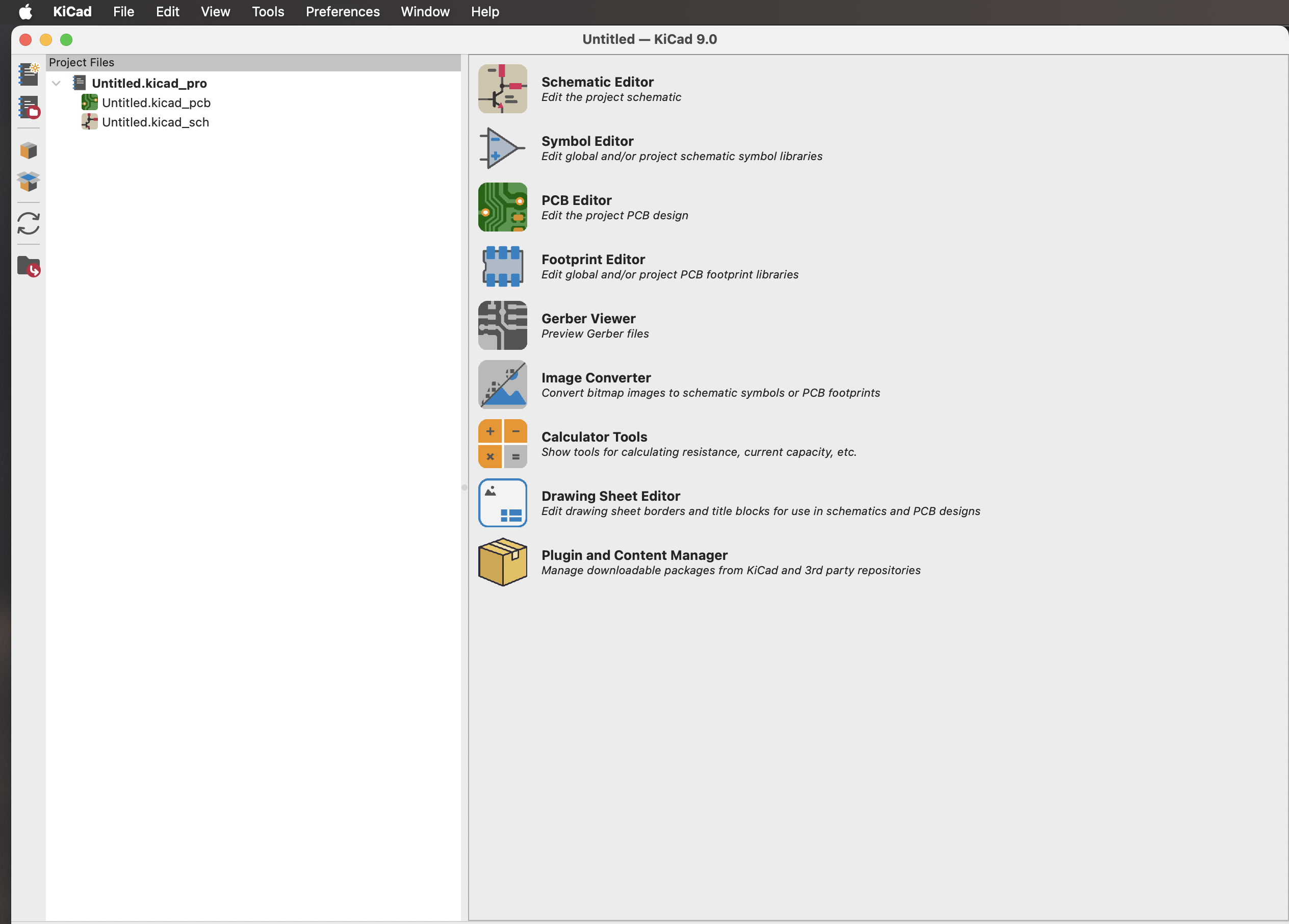
Within KiCad Project viewer:
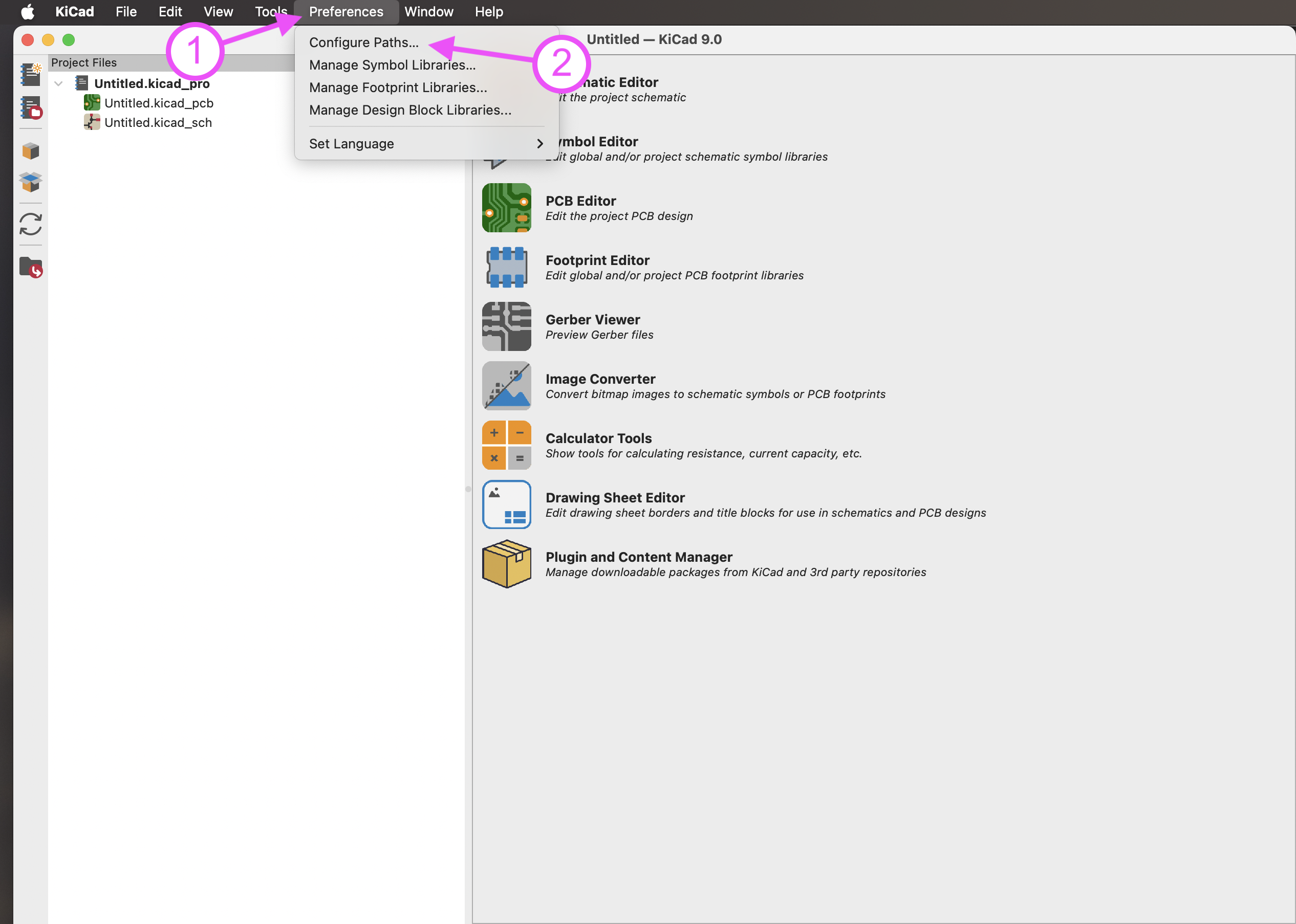
Click on Preferences->Configure Paths...
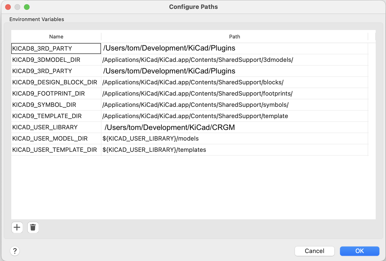
Perform the following actions:
/Users/Development/KiCad/CRGM/)Your screen should look something like this:
Click OK to save.
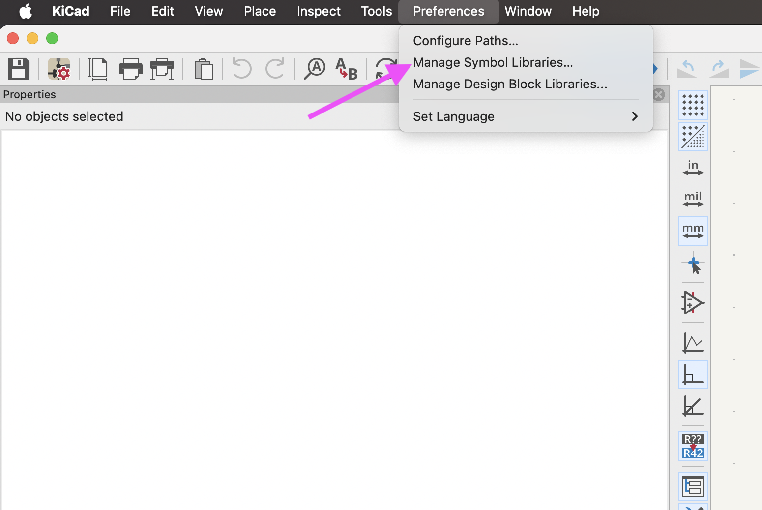
Within KiCad Schematic Editor, click Preferences->Manage Symbol Libraries...
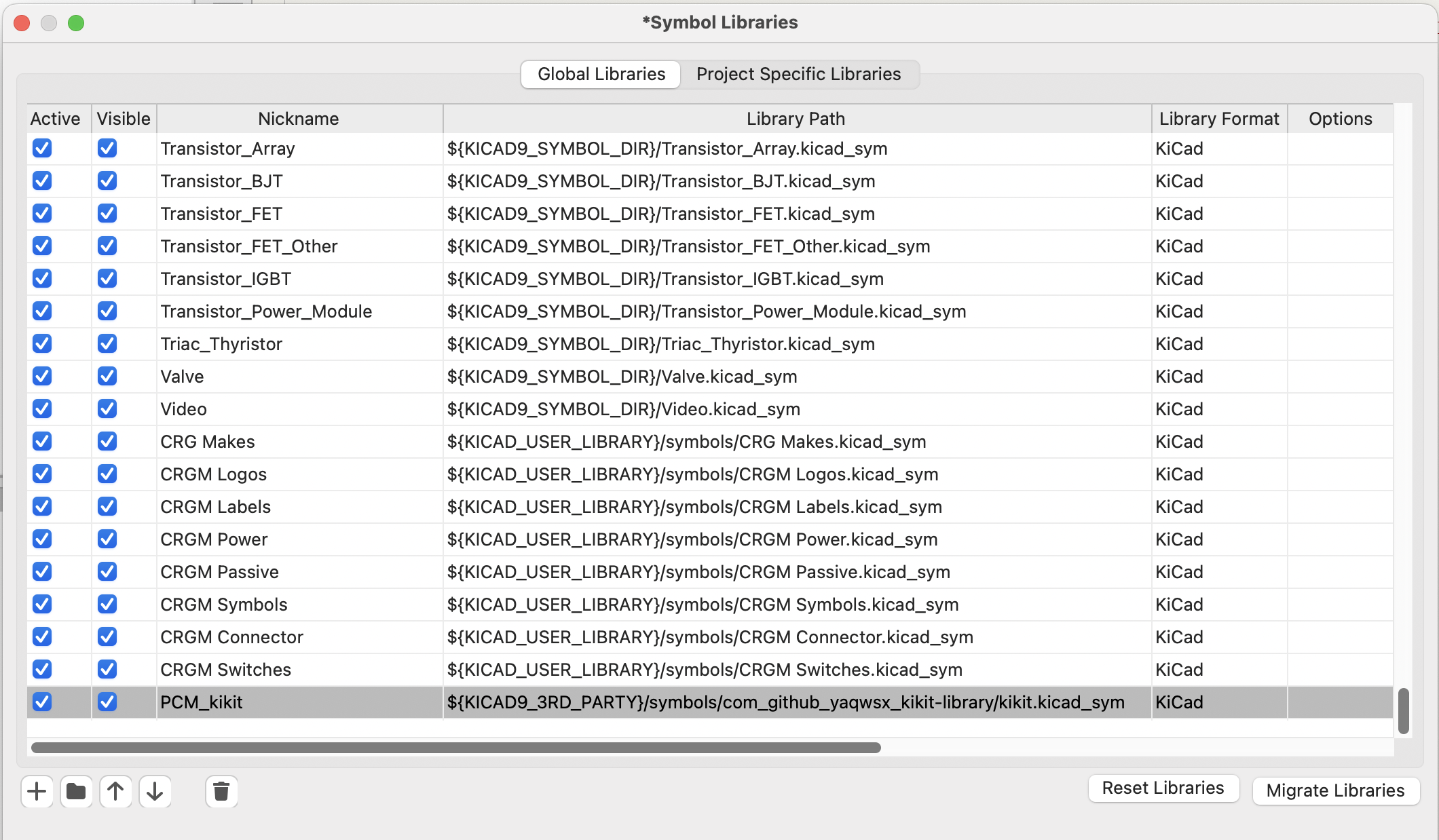
Add the following parameters by clicking +:
| Name | Value |
|---|---|
| CRG Makes | ${KICAD_USER_LIBRARY}/symbols/CRG Makes.kicad_sym |
| CRGM Connector | ${KICAD_USER_LIBRARY}/symbols/CRGM Connector.kicad_sym |
| CRGM Logos | ${KICAD_USER_LIBRARY}/symbols/CRG Makes.kicad_sym |
| CRGM Labels | ${KICAD_USER_LIBRARY}/symbols/CRGM Labels.kicad_sym |
| CRGM Power | ${KICAD_USER_LIBRARY}/symbols/CRGM Power.kicad_sym |
| CRGM Passive | ${KICAD_USER_LIBRARY}/symbols/CRGM Passive.kicad_sym |
| CRGM Symbols | ${KICAD_USER_LIBRARY}/symbols/CRGM Symbols.kicad_sym |
| CRGM Switches | ${KICAD_USER_LIBRARY}/symbols/CRGM Switches.kicad_sym |
Your parameters should look like this:
Within KiCad PCB Editor, click Preferences->Manage Footprint Libraries...
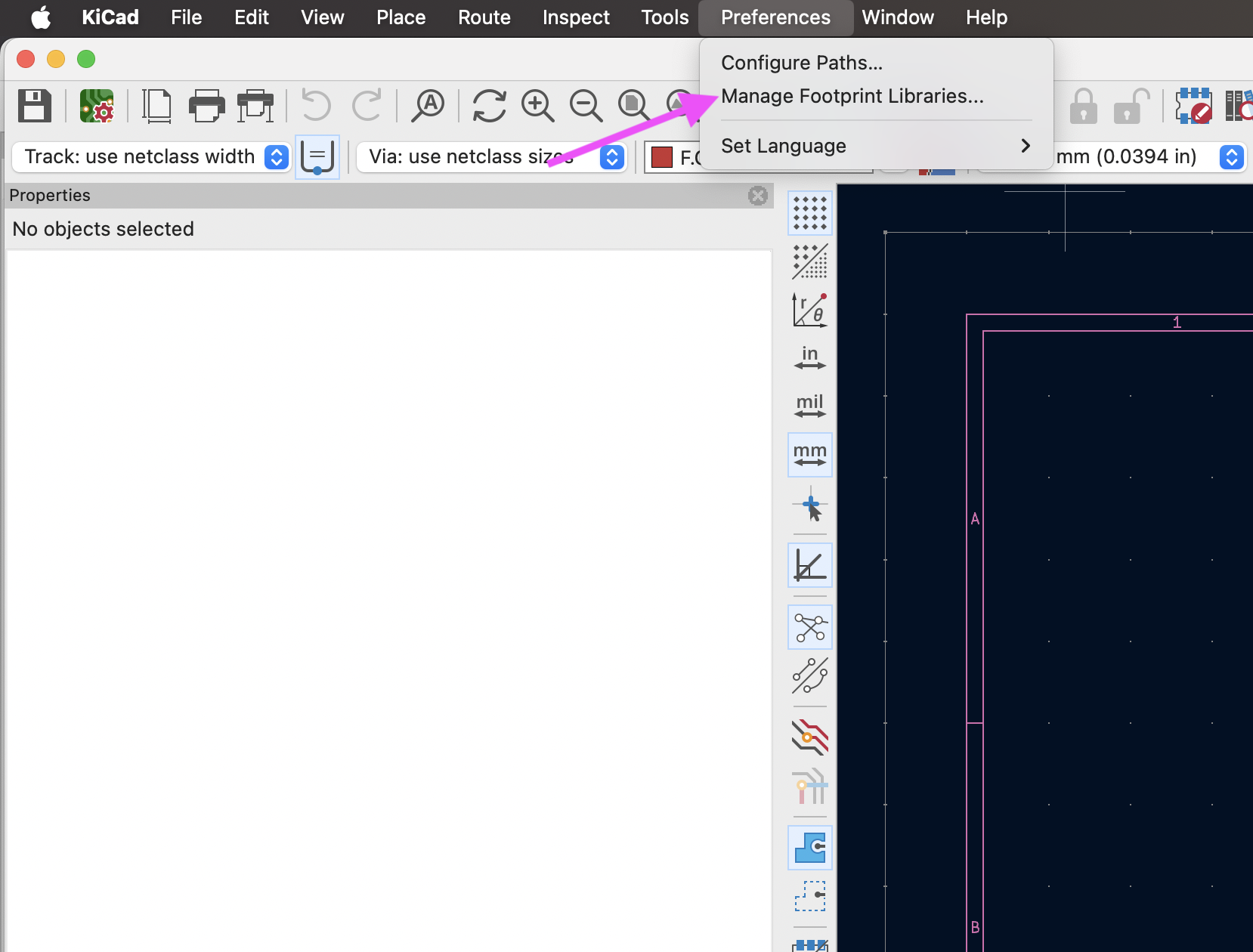
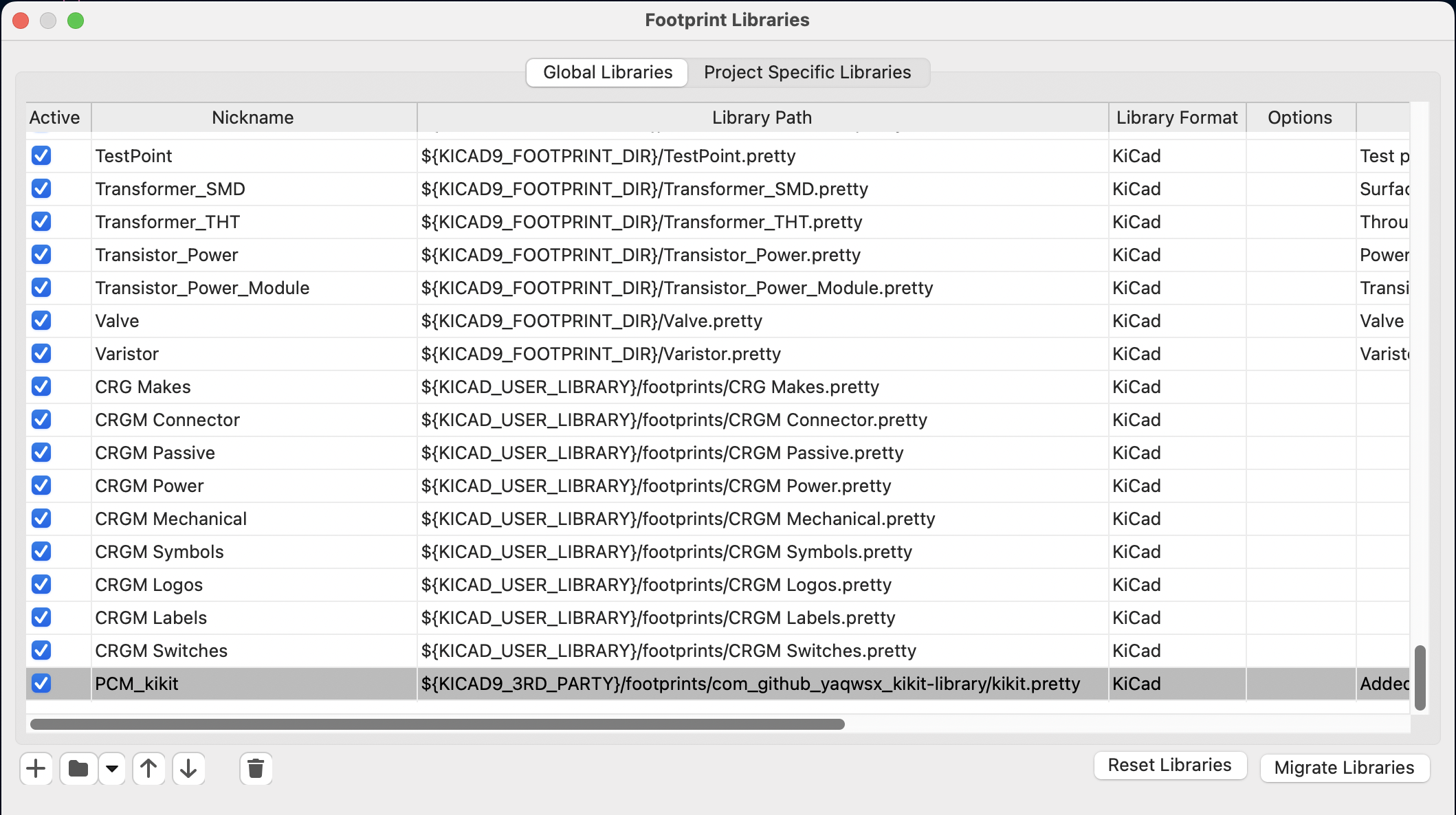
Add the following parameters by clicking +:
| Name | Value |
|---|---|
| CRG Makes | ${KICAD_USER_LIBRARY}/footprints/CRG Makes.pretty |
| CRGM Connector | ${KICAD_USER_LIBRARY}/footprints/CRGM Connector.pretty |
| CRGM Logos | ${KICAD_USER_LIBRARY}/footprints/CRG Makes.pretty |
| CRGM Labels | ${KICAD_USER_LIBRARY}/footprints/CRGM Labels.pretty |
| CRGM Mechanical | ${KICAD_USER_LIBRARY}/footprints/CRGM Mechanical.pretty |
| CRGM Power | ${KICAD_USER_LIBRARY}/footprints/CRGM Power.pretty |
| CRGM Passive | ${KICAD_USER_LIBRARY}/footprints/CRGM Passive.pretty |
| CRGM Switches | ${KICAD_USER_LIBRARY}/footprints/CRGM Switches.pretty |
| CRGM Symbols | ${KICAD_USER_LIBRARY}/footprints/CRGM Symbols.pretty |
Your parameters should look like this:
You may need to manually set the model path for some footprints. You do so by opening the footprint's properties by couple clicking on the footprint in the PCB editor.
Select 3D Models from the title bar:
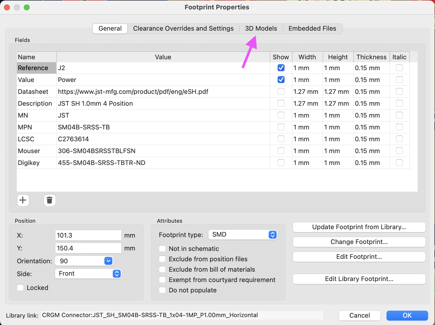
Set the value to: ${KICAD_USER_MODEL_DIR}/{your model}
Don't for get to select "Show" or your model will not display in 3d mode.
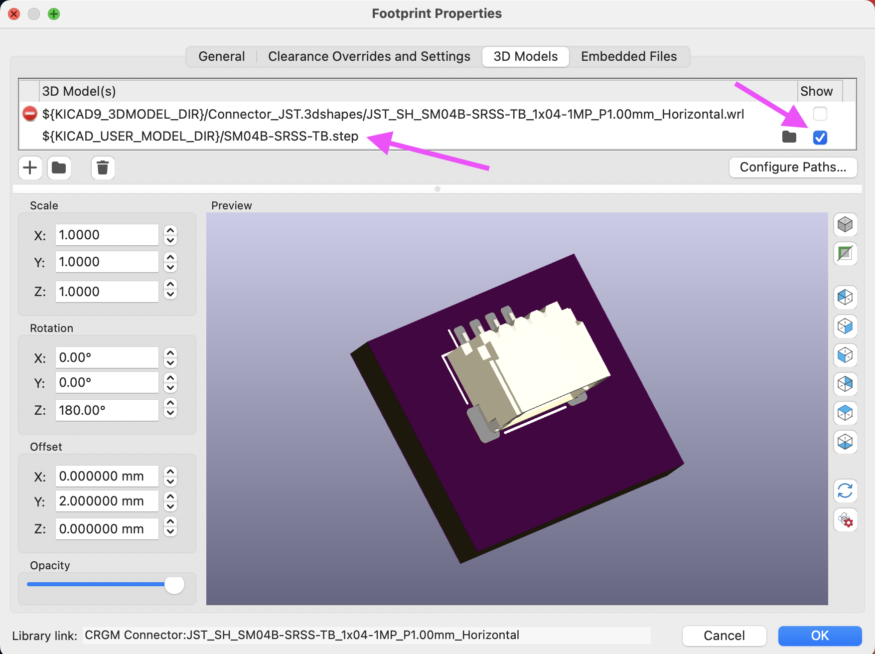
Happy making!
| Qty | Value | Footprint | References |
|---|---|---|---|
| 6 | ~ | CRGM Mechanical:TestPoint_Pad_D1.0mm | TP1, TP2, TP3, TP4, TP5, TP6 |
| 4 | 0.22uF | CRGM Passive:C_0603_1608Metric | C1, C4, C5, C10 |
| 4 | 100K | CRGM Passive:R_0603_1608Metric | R2, R8, R10, R11 |
| 3 | 0.1uF | CRGM Passive:C_0603_1608Metric | C3, C8, C9 |
| 3 | 4.99K | CRGM Passive:R_0603_1608Metric | R3, R4, R9 |
| 2 | 1uF | CRGM Passive:C_0603_1608Metric | C2, C6 |
| 2 | 300K | CRGM Passive:R_0603_1608Metric | R1, R5 |
| 2 | A1324LLHLT-T | CRGM Passive:SOT23W | U1, U3 |
| 2 | BAT54J | Diode_SMD:D_SOD-323F | D1, D2 |
| 1 | 10M | CRGM Passive:R_0603_1608Metric | R6 |
| 1 | 10uF | CRGM Passive:C_0603_1608Metric | C11 |
| 1 | 1M | CRGM Passive:R_0603_1608Metric | R7 |
| 1 | 1M | CRGM Passive:Bourns_TC33X_Vertical | RV1 |
| 1 | 2nF | CRGM Passive:C_0603_1608Metric | C7 |
| 1 | PESD3V3S1BL | CRGM Passive:DFN1006-2 | D7 |
| 1 | TLV9064 | CRG Makes:SOIC-14_3.9x8.7mm_P1.27mm | U2 |


SolderedElectronics/PIR-Movement-sensor-board-hardware-design
Hardware design, BOM, gerbers and 3D files for PIR-Movement-sensor-board designed by Soldered Electronics.

MotorDynamicsLab/Leviathan
Leviathan Main Controller for Voron 2 / Trident 3D Printers

itsmevjnk/MelbourneTrainTracker
Melbourne Train Tracker project repository (SIT210, T1/2025)


zarlicho/Qris-soundbox-esp32
QRIS Soundbox adalah sistem notifikasi pembayaran realtime yang dikembangkan untuk menerima dan memproses notifikasi pembayaran QRIS melalui protokol MQTT.

35 parts, built around the A1324LLHLT-T, TLV9064IDR-MS, FRC0603F1003TS and FRC0603F4991TS. The full list of its parts is on this page, with links to each part's symbol and footprint where PCBKit's library has them.
From the crgmakes/kicad-library repository on GitHub, at the commit this page was made from: the board is design_blocks/Aquarius.kicad_blocks/Current Sensor v3.1.kicad_block/Current Sensor v3.1.kicad_pcb and its schematic design_blocks/Aquarius.kicad_blocks/Current Sensor v3.1 AC.kicad_block/Current Sensor v3.1 AC.kicad_sch. PCBKit opens the board in the browser, with nothing to install.
Its repository states no licence, so its author keeps all rights: ask crgmakes before reusing the design.