
2 layers100 × 100 mm

PCB board to control my electronics workbench
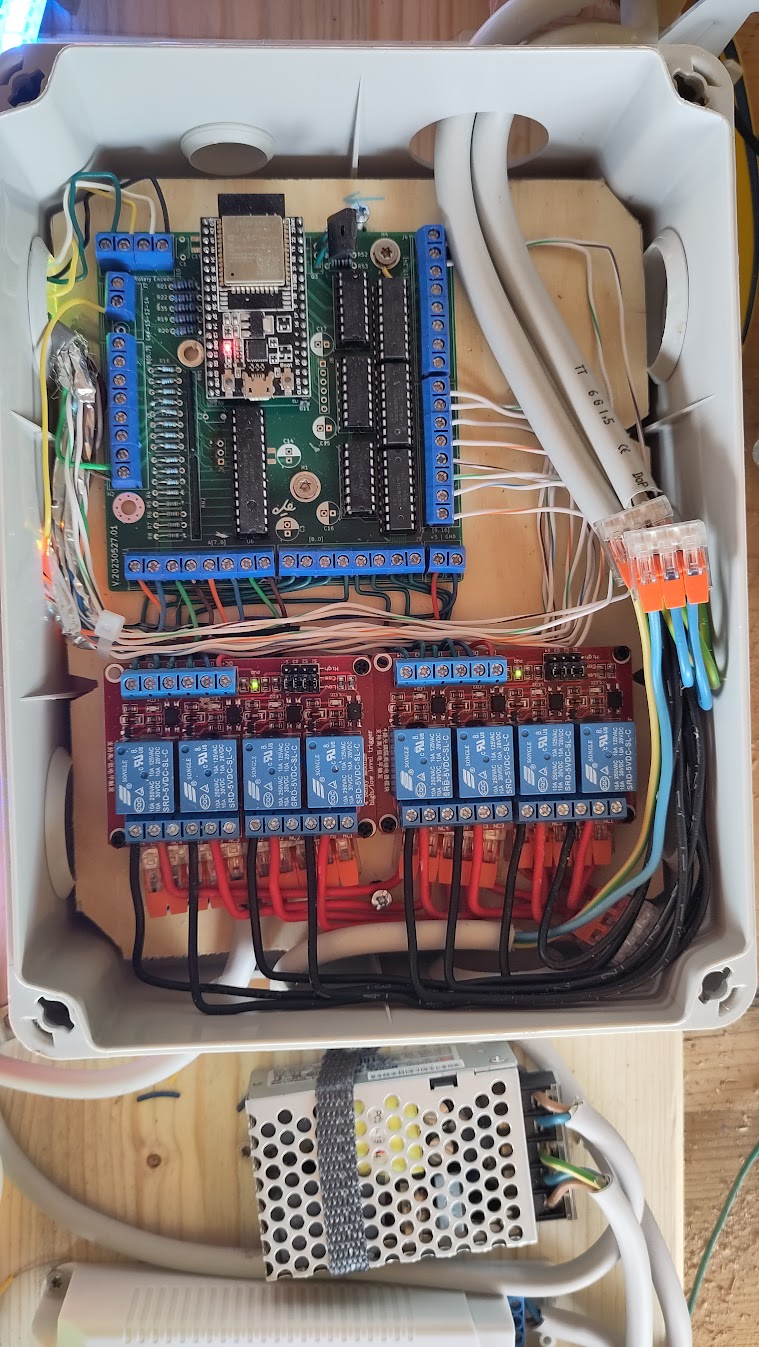
Workbench is an open-source printed circuit board by crgarcia12, from the crgarcia12/electronics-workbench-controller repository on GitHub. It is a 4-layer board of 99.9 × 99.8 mm with 70 parts on 127 nets, routed with 467 tracks and 3 vias.
It is built around the ESP32-DEVKITC-VE, 74HC595 and ULN2803A, with the IRL520PBF among its other parts. Its parts include 24 resistors, 19 capacitors, 10 connectors, 8 ICs and 1 transistor. It belongs with the ESP32 boards of this library.


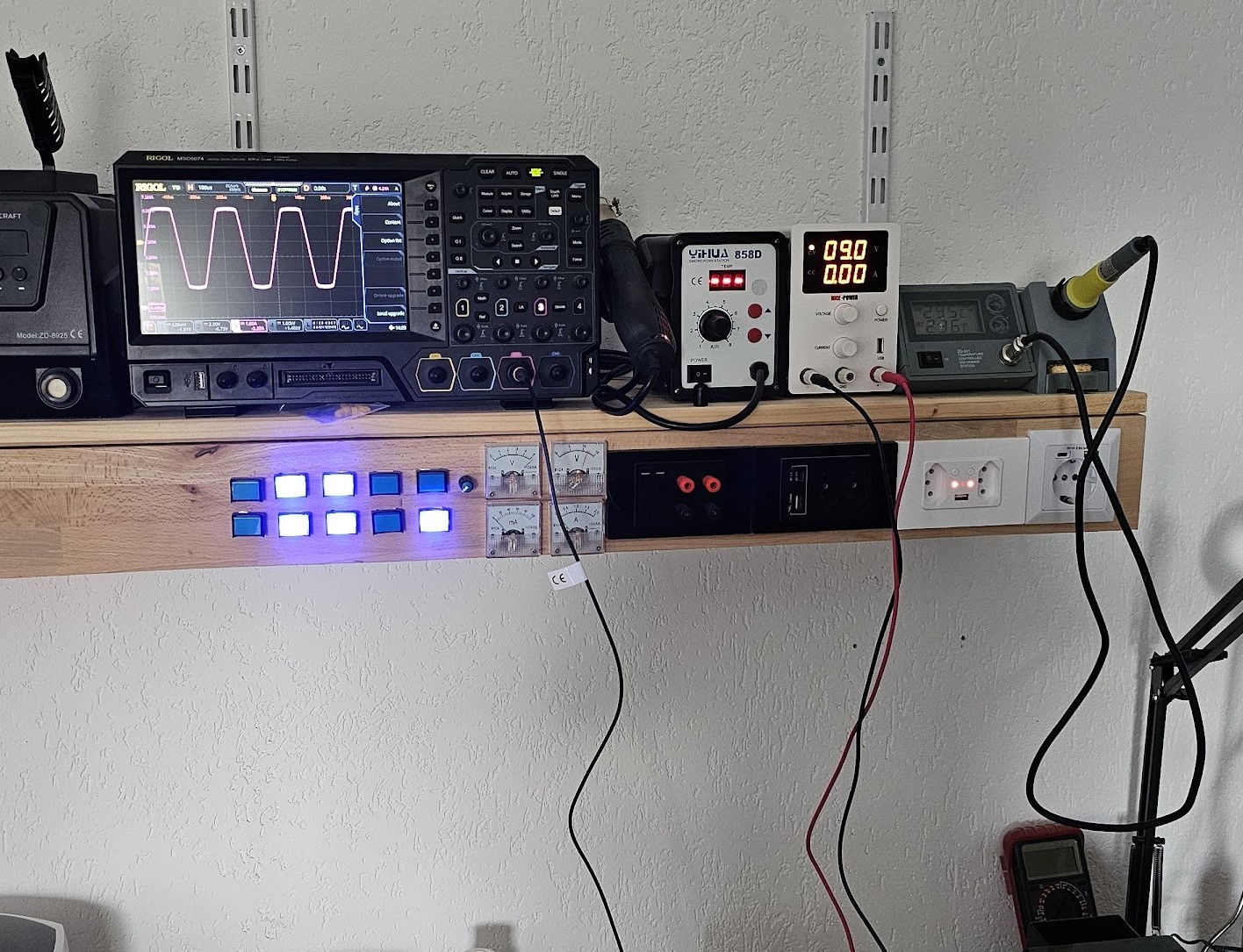
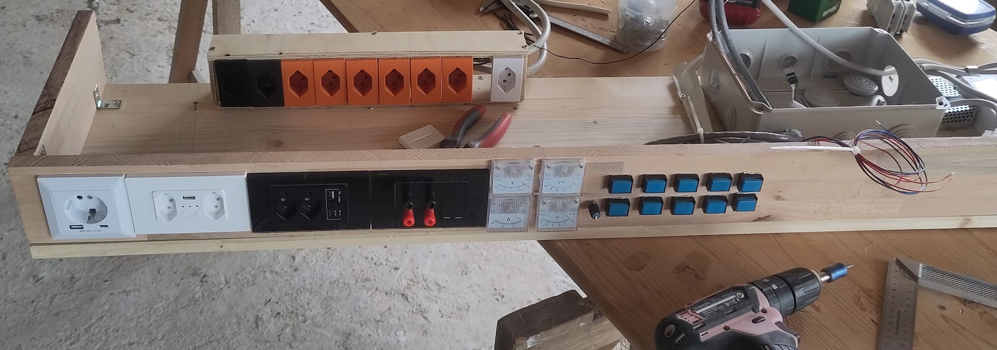
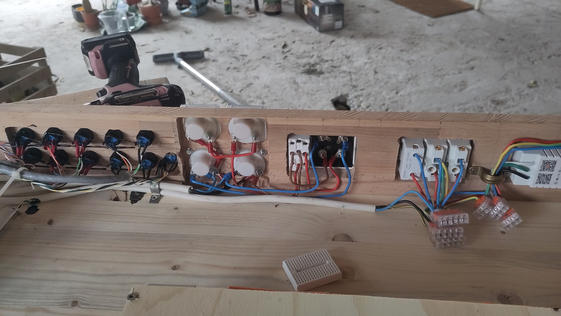
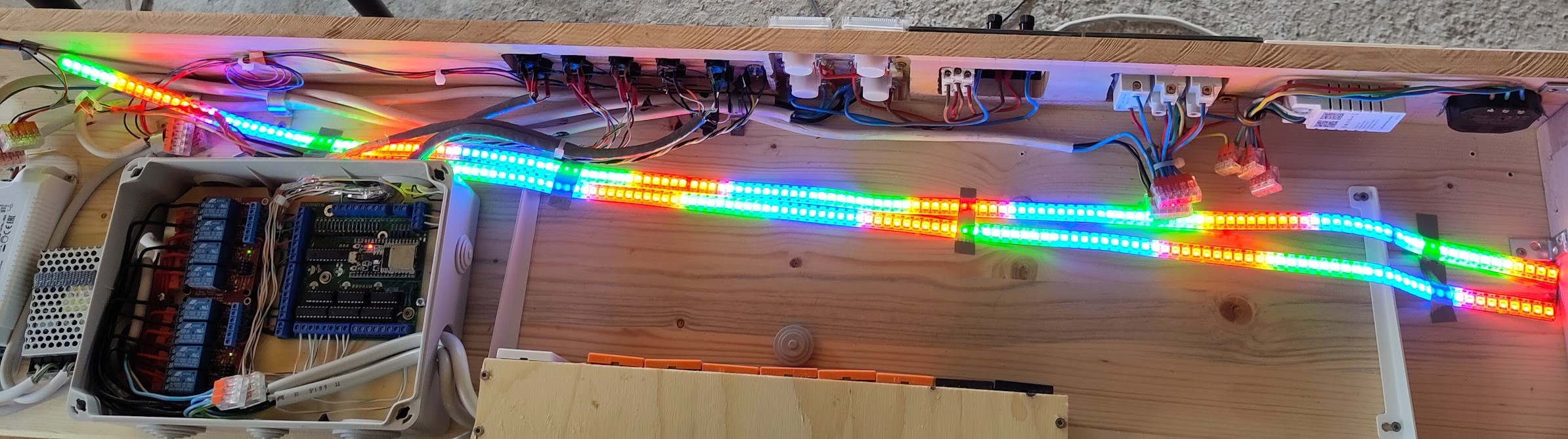
This project builds a shelf for electronic devices that can be controlled remotely or via a control pannel in the shelf
The board has:
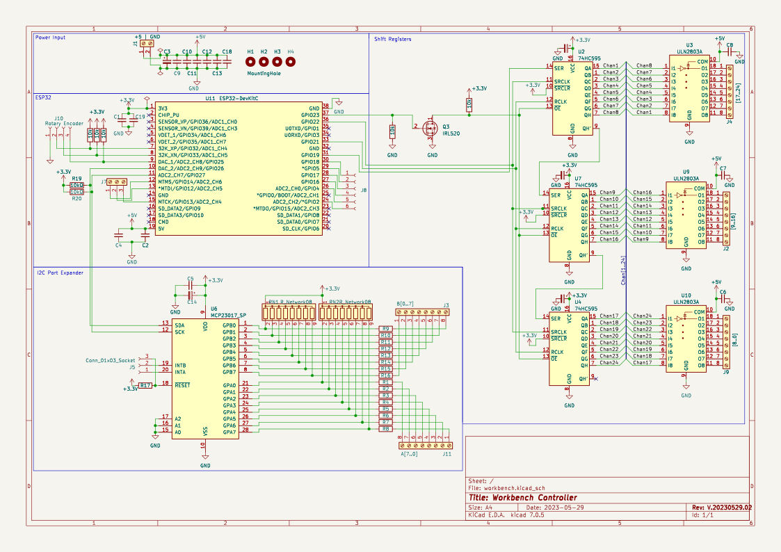
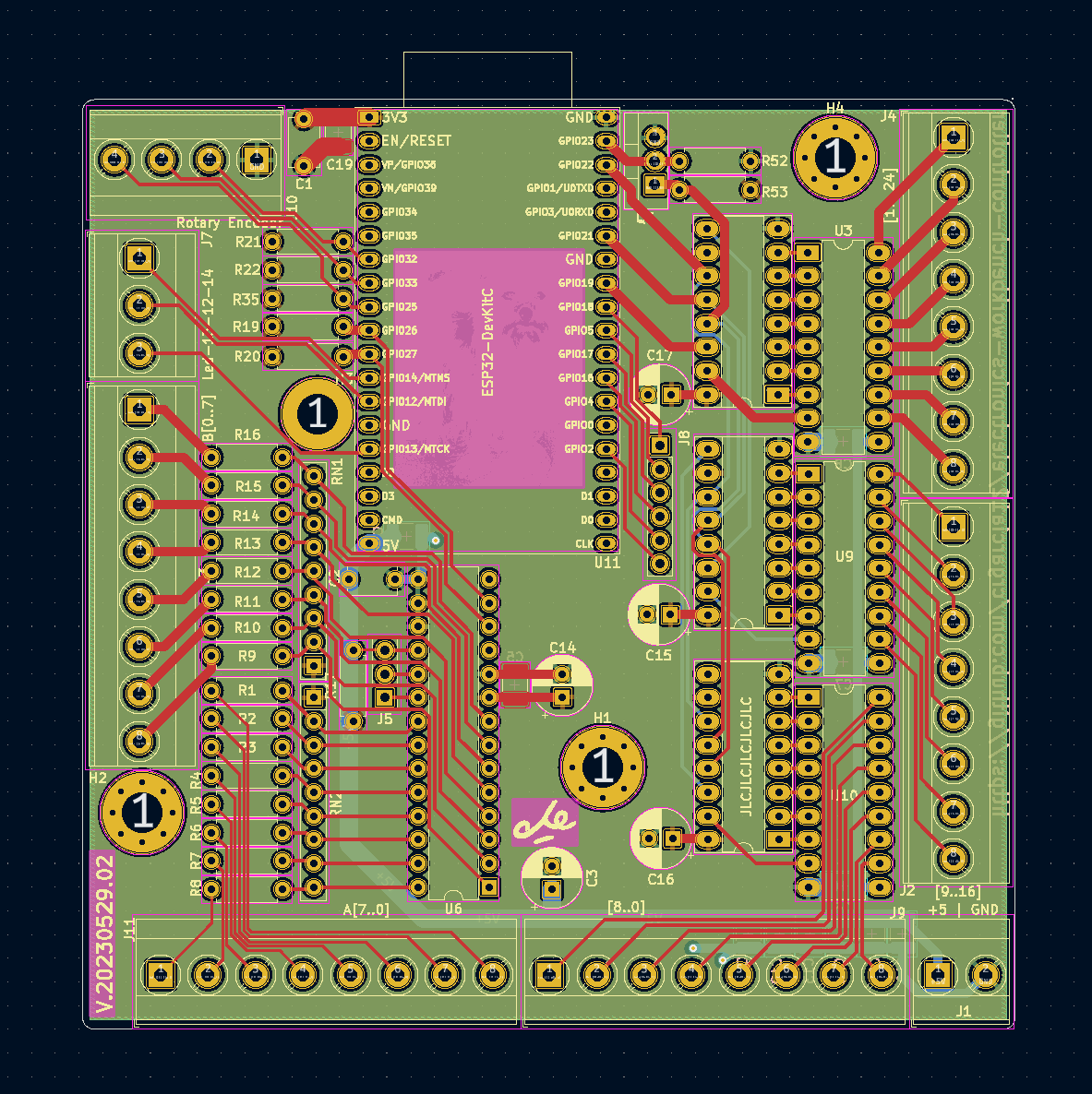
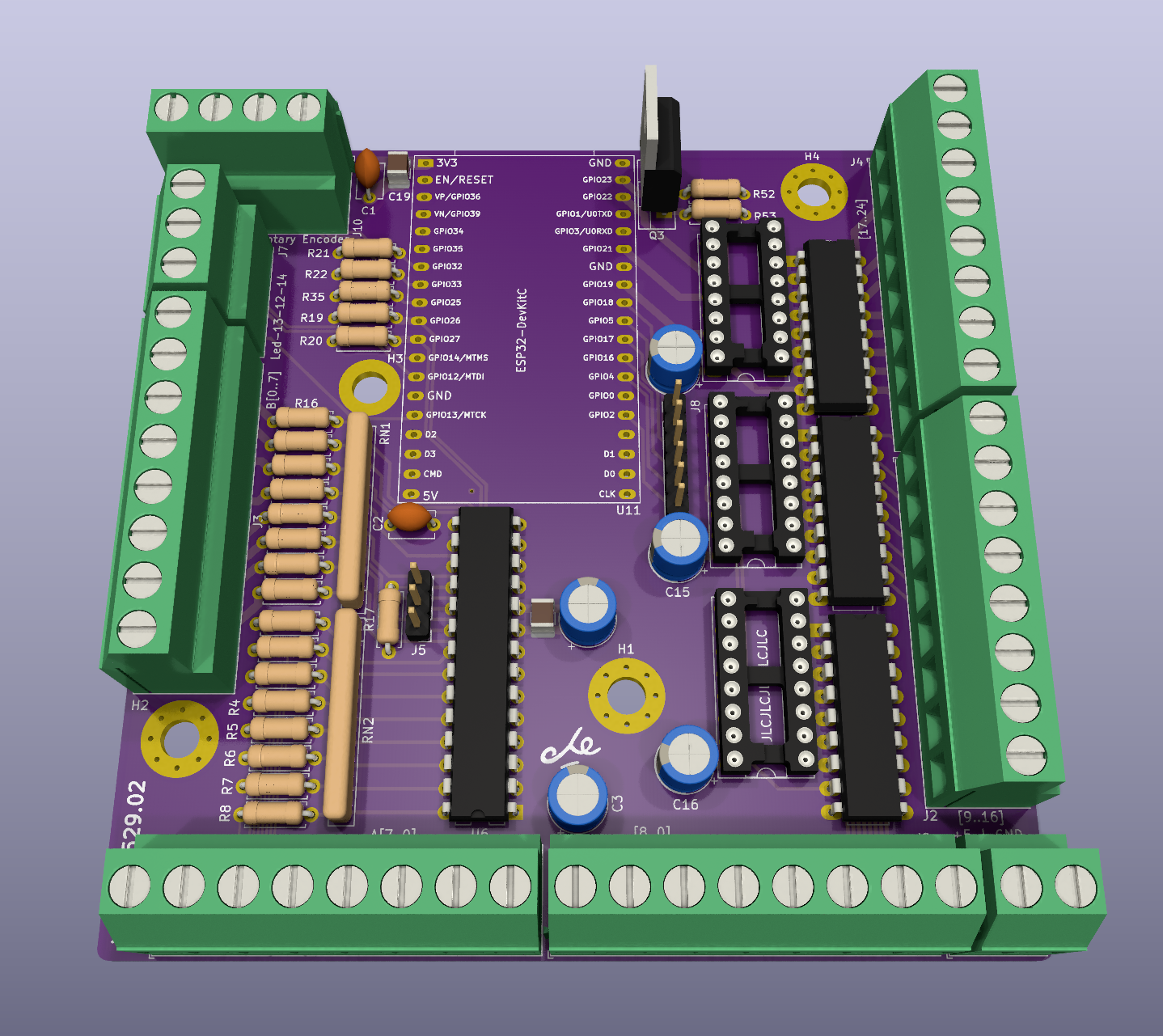
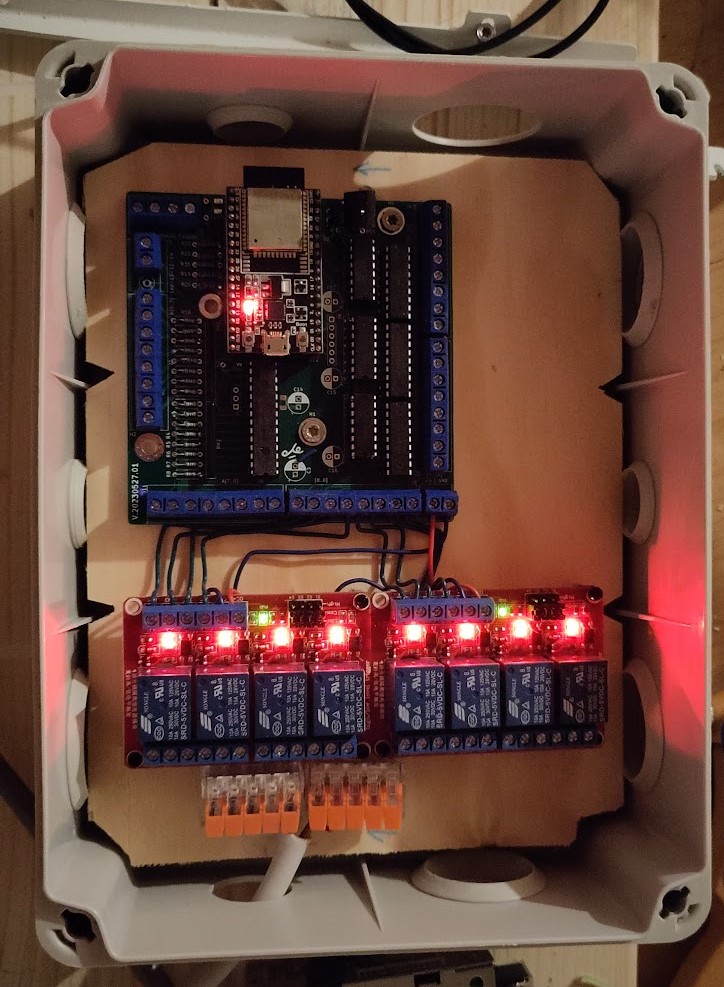
| Qty | Value | Footprint | References |
|---|---|---|---|
| 17 | R | Resistor_THT:R_Axial_DIN0207_L6.3mm_D2.5mm_P7.62mm_Horizontal | R1, R2, R3, R4, R5, R6, R7, R8, R10, R11, R12, R13, R14, R15, R16, R17 +1 |
| 12 | C | Capacitor_SMD:C_1210_3225Metric_Pad1.33x2.70mm_HandSolder | C4, C5, C6, C7, C8, C9, C10, C11, C12, C13, C18, C19 |
| 5 | 10k | Resistor_THT:R_Axial_DIN0207_L6.3mm_D2.5mm_P7.62mm_Horizontal | R21, R22, R35, R52, R53 |
| 5 | 10uF | Capacitor_THT:CP_Radial_D6.3mm_P2.50mm | C3, C14, C15, C16, C17 |
| 3 | 74HC595 | Package_DIP:DIP-16_W7.62mm_Socket_LongPads | U2, U4, U7 |
| 3 | MountingHole | MountingHole:MountingHole_4.3mm_M4_Pad_Via | H1, H2, H4 |
| 3 | ULN2803A | Package_DIP:DIP-18_W7.62mm_LongPads | U3, U9, U10 |
| 2 | 10kΩ | Resistor_THT:R_Axial_DIN0207_L6.3mm_D2.5mm_P7.62mm_Horizontal | R19, R20 |
| 2 | C | Capacitor_THT:C_Disc_D5.1mm_W3.2mm_P5.00mm | C1, C2 |
| 2 | R_Network08 | Resistor_THT:R_Array_SIP9 | RN1, RN2 |
| 1 | +5 | GND | TerminalBlock_Phoenix:TerminalBlock_Phoenix_MKDS-3-2-5.08_1x02_P5.08mm_Horizontal | J1 |
| 1 | A[7..0] | TerminalBlock_Phoenix:TerminalBlock_Phoenix_MKDS-3-8-5.08_1x08_P5.08mm_Horizontal | J11 |
| 1 | B[0..7] | TerminalBlock_Phoenix:TerminalBlock_Phoenix_MKDS-3-8-5.08_1x08_P5.08mm_Horizontal | J3 |
| 1 | Conn_01x03_Socket | Connector_PinHeader_2.54mm:PinHeader_1x03_P2.54mm_Vertical | J5 |
| 1 | Conn_01x06_Socket | Connector_PinHeader_2.54mm:PinHeader_1x06_P2.54mm_Vertical | J8 |
| 1 | ESP32-DevKitC | Esp:ESP32-DevKitC | U11 |
| 1 | IRL520 | Package_TO_SOT_THT:TO-220-3_Vertical | Q3 |
| 1 | LOGO | icons:depsi | G*** |
| 1 | LOGO | icons:che | G*** |
| 1 | Led-13-12-14 | TerminalBlock_Phoenix:TerminalBlock_Phoenix_MKDS-3-3-5.08_1x03_P5.08mm_Horizontal | J7 |
| 1 | MCP23017_SP | Package_DIP:DIP-28_W7.62mm | U6 |
| 1 | MountingHole | MountingHole:MountingHole_4.3mm_M4_DIN965_Pad | H3 |
| 1 | Rotary Encoder | TerminalBlock_Phoenix:TerminalBlock_Phoenix_MKDS-3-4-5.08_1x04_P5.08mm_Horizontal | J10 |
| 1 | [17..24] | TerminalBlock_Phoenix:TerminalBlock_Phoenix_MKDS-3-8-5.08_1x08_P5.08mm_Horizontal | J4 |
| 1 | [8..0] | TerminalBlock_Phoenix:TerminalBlock_Phoenix_MKDS-3-8-5.08_1x08_P5.08mm_Horizontal | J9 |
| 1 | [9..16] | TerminalBlock_Phoenix:TerminalBlock_Phoenix_MKDS-3-8-5.08_1x08_P5.08mm_Horizontal | J2 |

becem0/esp32-giant-chronometer
?? Giant 6-digit 7-segment race chronometer powered by ESP32, 24V COB LED strips, custom KiCad 10 PCB, and SIM800L GSM telemetry.

OverInvented/Flippy
The code needed to build a mechanical 7-segment display that uses electromagnets to display characters


niteshkadyan/Hearty-LED-Necklace-Badge
Kicad project files and Android app for the Hearty LED wearable necklace cum badge

julianschick/flipdot-brose
Microcontroller code (ESP32) and Circuit Design for controlling Brose Flipdot Modules.
It measures 99.9 × 99.8 mm and has 4 copper layers, 1.6 mm thick.
70 parts, built around the ESP32-DEVKITC-VE, 74HC595, ULN2803A and IRL520PBF. The full list of its parts is on this page, with links to each part's symbol and footprint where PCBKit's library has them.
From the crgarcia12/electronics-workbench-controller repository on GitHub, at the commit this page was made from: the board is PCB/workbench-02/workbench.kicad_pcb and its schematic PCB/workbench-01-jlcpcb/workbench.kicad_sch. PCBKit opens the board in the browser, with nothing to install.
Its repository states no licence, so its author keeps all rights: ask crgarcia12 before reusing the design.