
4 layers45 × 32 mm
Templog mainboard
Michael-Manning/E-Paper-Climate-Logger
Firmware, PCB, and enclosure for the Weathergotchi E-Paper climate logger.
68 parts457MIT
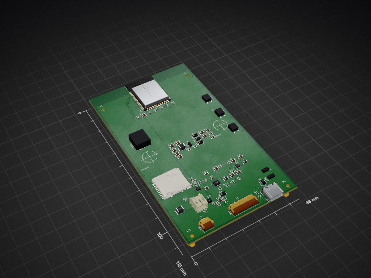
This repository holds the open hardware (KiCad) and project documentation for a small e-reader. Docs follow the Colophon method: a Brief (this file), Decisions (docs/adr/), a Log (docs/research-log.md), a Runbook…
Ereader is an open-source printed circuit board by Craft-Code-Systems, from the Craft-Code-Systems/mini-ereader repository on GitHub, published under the MIT licence. It is a 4-layer board of 66 × 115 mm with 81 parts on 59 nets, routed with 341 tracks and 115 vias.
It is built around the ESP32-S3-WROOM-1-N16R8, LM3630ATME and USBLC6-2SC6, with the MBR0530, SLLB510200 and SI1308EDL among its other parts. Its parts include 17 resistors, 6 ICs, 5 connectors, 4 switches and 3 capacitors. It belongs with the ESP32 boards of this library.


A pocket, frontlit e-paper reader you can build and hack. ESP32-S3 + 4.26" E-Paper (800×480) + tunable-white frontlight, USB-C charged, LiPo powered.
This repository holds the open hardware (KiCad) and project documentation
for a small e-reader. Docs follow the Colophon
method: a Brief (this file), Decisions (docs/adr/), a Log
(docs/research-log.md), a Runbook (docs/runbook.md), and a Changelog.
One KiCad project, one source of truth. The board lives at the repo root:
ereader.kicad_pcb, with the electrical design in theereader-*.mddocs —ereader-connection-list.md(net-by-net source of truth),ereader-schematic.md(subsystem schematic),ereader-pcb-design.md(full spec),ereader-footprints.md(BOM/footprint picklist) — and theereader-kicad.netnetlist. (Rev C — placed, planed, stitched, DRC-ruled; routing pending.) An earlier, simplerhardware/reference spec was removed onceereader.*superseded it; the historical comparison is indocs/research-log.md. The Rev C parts are reconciled into the ADRs: 0006 (power) supersedes 0003 and 0007 (frontlight) supersedes 0005.
Commercial e-readers are closed and hard to modify. This is a compact, documented reference design — cheap parts, two-layer board, hand- or JLCPCB-assemblable — for reading plain text / EPUB on a persistent, sunlight-readable display with an adjustable frontlight and Wi-Fi sync. A buildable learning platform, not a product.
In scope
Out of scope (for now)
kicad-cli ERC/DRC/export).v0.1 — design captured; reviewable schematic in ereader-schematic.md; native Eeschema .kicad_sch + routed PCB not yet drawn in KiCad.
ereader-pcb-design.md + ereader-connection-list.mddocs/adr/0001–0005ereader.* placed + config that opens cleanlykicad-cli ERC/DRC/export workflowereader-schematic.md; native Eeschema capture + ERC clean pendingLive verification state: the milestone checklist above.
| # | Decision |
|---|---|
| 0001 | ESP32-S3-WROOM-1 as the MCU |
| 0002 | 4.26" 800×480 E-Paper + laminated tunable frontlight |
| 0003 | USB-C + 1S LiPo, load-share, 3.3 V LDO (superseded by 0006) |
| 0004 | Native-USB programming (no UART bridge) |
| 0005 | Dual boost constant-current frontlight driver (superseded by 0007) |
| 0006 | I2C-managed power path: BQ25628E + TPS62840 + MAX17048 |
| 0007 | LM3630A single-boost dual-sink frontlight driver |
| 0008 | Navigation input: 3 side buttons + ALPS SLLB510200 lever switch |
# Open the board in KiCad 8
kicad ereader.kicad_pro

# Read the electrical design (source of truth)
less ereader-connection-list.md
See docs/runbook.md for capture, verification,
CI, fabrication, and bring-up. Component-level detail lives in
ereader-pcb-design.md and
ereader-schematic.md.
README.md              This Brief
CHANGELOG.md           Project history
ereader.*              The KiCad board (project, PCB, netlist, cmp)
ereader-*.md           Electrical source of truth: connection-list, schematic, pcb-design, footprints, README
ereader.pretty/        Project footprints (side tactile, ALPS SLLB5 lever)
ereader.3dshapes/      Simple 3D bodies for the project footprints
fp-lib-table           Registers the ereader.pretty footprint library
fab.py                 Gerber/drill export helper (preflight-gated)
gen_netlist.py         SKiDL netlist generator (real symbols → clean import)
preflight.py           Board↔netlist parity check (CI gate; fab.py guard)
docs/
  adr/                 Decisions (0001–0008 + template)
  research-log.md      Dated exploration notes
  runbook.md           Capture / verify / fabricate / bring-up
templates/             Colophon document templates (for ongoing use)
.github/workflows/ CI (KiCad ERC/DRC/export)MIT for code, hardware, and documentation. (This repository started from the Colophon template; the doc method is reused under MIT here — the template's separate CC BY methodology license has been removed.)
| Qty | Value | Footprint | References |
|---|---|---|---|
| 7 | 4.7uF/25V | Capacitor_SMD:C_0805_2012Metric | CE1, CE2, CE3, CE4, CE5, CE6, CE10 |
| 6 | 0.1uF | Capacitor_SMD:C_0402_1005Metric | CGA, CPM2, CU2, CU3, CU4, CU5 |
| 5 | 100k | Resistor_SMD:R_0402_1005Metric | R3, R4, R5, R6, R7 |
| 5 | 10uF | Capacitor_SMD:C_0805_2012Metric | CB, CI, CO, CPM, CS |
| 4 | 10k | Resistor_SMD:R_0402_1005Metric | R12, R13, R14, R15 |
| 4 | 4.7k | Resistor_SMD:R_0402_1005Metric | R8, R9, R10, R11 |
| 4 | M2 | MountingHole_2.2mm_M2 | H1, H2, H3, H4 |
| 3 | 1uF | Capacitor_SMD:C_0402_1005Metric | C4I, CEN, CGB |
| 3 | 1uF/25V | Capacitor_SMD:C_0603_1608Metric | CE7, CE8, CE9 |
| 3 | FID | Fiducial_1mm_Mask2mm | FID1, FID2, FID3 |
| 3 | MBR0530 | Diode_SMD:D_SOD-123 | DE1, DE2, DE3 |
| 2 | 5.1k | Resistor_SMD:R_0402_1005Metric | R1, R2 |
| 1 | 1.65k | Resistor_SMD:R_0402_1005Metric | R17 |
| 1 | 1M | Resistor_SMD:R_0402_1005Metric | RE2 |
| 1 | 1uF | Capacitor_SMD:C_0603_1608Metric | CV |
| 1 | 1uH | Inductor_SMD:L_0805_2012Metric | LC |
| 1 | 2.2R | Resistor_SMD:R_0402_1005Metric | RE1 |
| 1 | 2.2uF/25V | Capacitor_SMD:C_0805_2012Metric | CF |
| 1 | 2.2uH | Inductor_SMD:L_0805_2012Metric | L1 |
| 1 | 22uF | Capacitor_SMD:C_0805_2012Metric | CU1 |
| 1 | 22uH | Inductor_SMD:L_1210_3225Metric | L2 |
| 1 | 267k | Resistor_SMD:R_0402_1005Metric | R16 |
| 1 | 4.7uF | Capacitor_SMD:C_0603_1608Metric | CRG |
| 1 | 47nF | Capacitor_SMD:C_0402_1005Metric | CBT |
| 1 | 47uH | Inductor_SMD:L_1210_3225Metric | LE |
| 1 | BOOT | ereader:JumperPad_2P_P2.0mm | JP5 |
| 1 | BQ25628E | ereader:WQFN-HR18__RYK_TEX | U2 |
| 1 | BTN_A | ereader:WE_WS-TASU_436351045816 | SW1 |
| 1 | BTN_B | ereader:WE_WS-TASU_436351045816 | SW2 |
| 1 | BTN_C | ereader:WE_WS-TASU_436351045816 | SW3 |
| 1 | Battery_1S | Connector_JST:JST_PH_S2B-PH-K_1x02_P2.00mm_Horizontal | J5 |
| 1 | EPD_FPC_24P | Connector_FFC-FPC:Hirose_FH12-24S-0.5SH_1x24-1MP_P0.50mm_Horizontal | J2 |
| 1 | ESP32-S3-WROOM-1-N16R8 | RF_Module:ESP32-S3-WROOM-1 | U1 |
| 1 | FL_FPC_6P | Connector_FFC-FPC:Hirose_FH12-6S-0.5SH_1x06-1MP_P0.50mm_Horizontal | J3 |
| 1 | LM3630A | ereader:BGA12N50P4X3_196X146X62 | U4 |
| 1 | MAX17048 | ereader:SON50P200X200X80-9N | U3 |
| 1 | RESET | ereader:JumperPad_2P_P2.0mm | JP6 |
| 1 | SLLB510200 | ereader:ALPS_SLLB5_Lever | SW4 |
| 1 | Schottky_30V | Diode_SMD:D_SOD-123 | D1 |
| 1 | Si1308EDL | Package_TO_SOT_SMD:SOT-23 | QE |
| 1 | TPS62840 | ereader:SON50P200X200X80-9N | U5 |
| 1 | USB-C-16P | Connector_USB:USB_C_Receptacle_HRO_TYPE-C-31-M-12 | J1 |
| 1 | USBLC6-2SC6 | Package_TO_SOT_SMD:SOT-23-6 | U6 |
| 1 | microSD | ereader:HRS_DM3AT-SF-PEJM5 | J4 |
It measures 66 × 115 mm and has 4 copper layers, 1.6 mm thick.
81 parts, built around the ESP32-S3-WROOM-1-N16R8, LM3630ATME, USBLC6-2SC6 and MBR0530. The full list of its parts is on this page, with links to each part's symbol and footprint where PCBKit's library has them.
From the Craft-Code-Systems/mini-ereader repository on GitHub, at the commit this page was made from: the board is ereader.kicad_pcb. PCBKit opens the board in the browser, with nothing to install.
Its repository publishes it under the MIT licence: you may reuse it on that licence's terms (keep the author's notice, and for a copyleft licence share your changes alike).
Michael-Manning/E-Paper-Climate-Logger
Firmware, PCB, and enclosure for the Weathergotchi E-Paper climate logger.


NoctaLabs-Sh/Nocta-One-Hardware
Open hardware for the Nocta vault: an offline password manager with a 2.7 inch e-ink screen. KiCad schematic, board layout, gerbers and BOM. CERN-OHL-S v2.


