Skip to the content
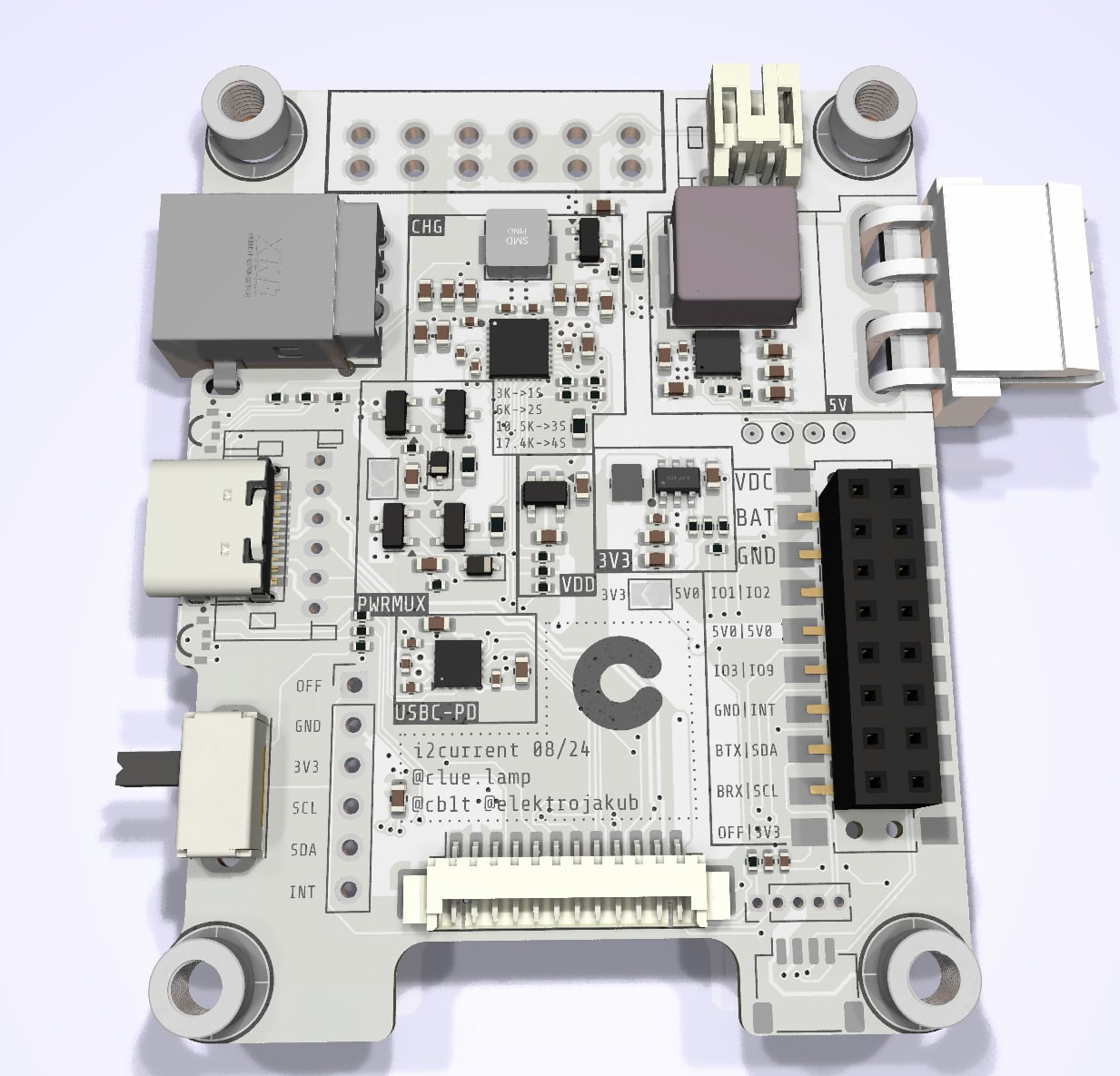
2 layers50 × 64 mmI2current, the printed circuit board in 3D

The Raison d'être of this board is to be a powerful, extensible, and affordable replacement for hotglueing a random powerbank into your next portable small-scale electronic project.

Size
50 × 64 mm
Copper layers
2
Thickness
1.6 mm
Parts
158
Nets
88
Pads
507
Tracks, vias
1,408, 238
Pours
27
Routed
Yes
KiCad
KiCad 9.0 (file 20241229)
Created
24 Mar 2024
Updated
16 Dec 2025

Overview

I2current is an open-source printed circuit board by cr1tbit, from the cr1tbit/i2current repository on GitHub. It is a 2-layer board of 50 × 64 mm with 158 parts on 88 nets, routed with 1,408 tracks and 238 vias.

It is built around the PY32F002AW15U6TR, FUSB302B01MPX and MT2492, with the TPS56637RPAR, 74HC4066PW,118-JSM and BQ25792RQMR among its other parts. Its parts include 51 capacitors, 43 resistors, 13 diodes, 10 ICs and 4 transistors.

Main components

12

README

README.md

I2Current powerboard

The Raison d'être of this board is to be a powerful, extensible, and affordable replacement for hotglueing a random powerbank into your next portable small-scale electronic project.

The largest benefit comes from the I2C interface - If, for example, a Raspberry Pi is powered with this board, it can actually check the battery state, if DC-jack is currently charging the device, or even see the power draw of other peripherals connected to this system.

The board is most useful for powering devices requiring peak power draw between 15W-60W.

For devices requiring less power, the cost overhead becomes a bit too much - alternative solutions on aliexpress, albeit not as much versatile, can cost less than $3 (this board costs ~$10, ordering 20 units from JLCPCB).
image

Sub-components

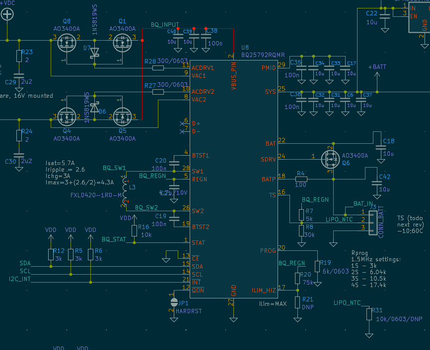
BQ25792 Li-Ion charger

Specs:

  • 3.6-24V input, max 3A (realistically, ~60W)
  • Input voltage independent from battery pack (buck-boost built-in)
  • Input from USB-C and/or DC barrel jack.
  • Can provide up to 3.33A@20V output to the same USB-C port
  • can work with 1S-4S (cells in series)
  • output current 5A (with 4 cells (~16V), up to ~80W output)
  • Works properly without battery pack too (can work as buck-boost power supply)
  • Many parameters configurable via i2c
  • Various battery/input/output voltages/currents readout
image

This charger is incredibly universal, costing around 1$ it provides versatility for many types of projects.

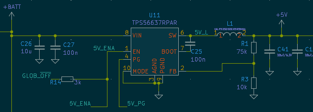
TPS56637 5V output step-down converter
image

It can provide up to 6A (30W) on output. However, it requires atleast 2S packet to be usable.

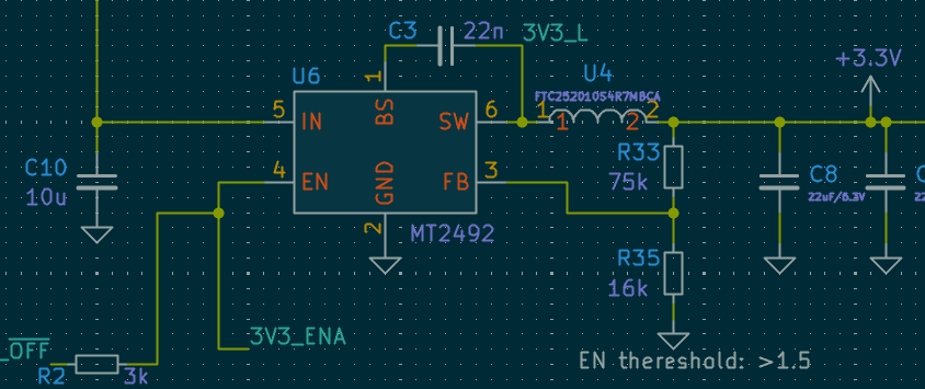
MT2492 3V3 DC-DC
image

This converter supports optional built-in ESP32-C3 controller, and can also be accesed via output pins

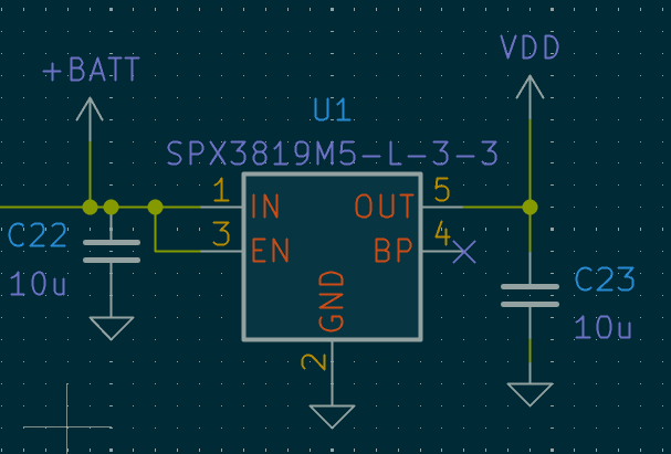
SPX3819M5-L-3-3 3V3 LDO
image

This low-power stabilizer provides power to onboard devices and some circuitry. It cannot be turned off, in contrast to 2 other converters.

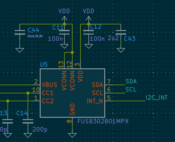
FUSB302B Power Delivery controller
image

This device is controlled via i2c, and can be used to negotiate up to 5A/20V from compatible USB-C chargers.

Arduino library is available.

Connectors

Output 2.54 connector

This connector has been designed for low-profile goldpin socket connector (the male header actually goes through the holes in the PCB)

Shield can be designed, utilizing this connector.

Picoblade connector

This connector is dedicated for devices, where a "master" board sits somewhere else in the system.

Battery connector

  • Battery input
  • NTC resistor input (every battery pack should contain one, more on that later)
  • GND
  • Battery output (coming from BQ charger, provides stable voltage when baterry is depleated or missing)
  • GLOB_OFF (pin for external power-off switch)
  • VDC_IN (same as from barrel jack input)

More to come...

this board has many more fun quirks - I'll describe more details at a later date.

  • optional mini front panel with OLED
  • Passive-PoE input
  • standalone 4-channel WLED controller
  • USB data lanes passthrough for 2 connectors and built-in ESP32
Todo - document:
  • Li-ion safety guide
  • USB passthrough
  • GLOB_OFF usage
  • Pinout description for every connector
  • 1S-4S config and limitations

Sponsors

Developent of this board is supported by Clue.lamp.

Check them out, the device looks really nice, and utilizes state-of-the-art electronic design for both wired and wireless usage :)

Parts

158
QtyValueFootprintReferences
18100nCapacitor_SMD:C_0402_1005MetricC11, C12, C19, C20, C25, C26, C27, C35, C36, C38, C42, C43, C45, C46, C48, C49 +2
1810u/25VCapacitor_SMD:C_0603_1608MetricC2, C10, C17, C18, C22, C23, C24, C28, C31, C32, C33, C34, C37, C39, C40, C47 +2
12TestPointTestPoint:TestPoint_Pad_D1.0mmTP2, TP5, TP6, TP7, TP8, TP9, TP10, TP11, TP12, TP13, TP14, TP20
103kResistor_SMD:R_0402_1005MetricR2, R5, R6, R12, R14, R19, R22, R27, R28, R29
7LEDLED_SMD:LED_0603_1608MetricD1, D2, D3, D4, D7, D12, D13
6TestPointCritbit_lib:Nano_testpad_0.5x1.0mmTP1, TP17, TP18, TP19, TP21, TP22
510kResistor_SMD:R_0402_1005MetricR16, R18, R25, R26, R40
53k/0603Resistor_SMD:R_0603_1608MetricR10, R41, R42, R43, R44
575kResistor_SMD:R_0603_1608MetricR1, R20, R33, R38, R39
4100Resistor_SMD:R_0402_1005MetricR4, R11, R15, R17
422uF/25VCapacitor_SMD:C_1206_3216MetricC1, C15, C41, C50
4AON7544easyeda2kicad:DFN-8_L3.3-W3.3-P0.65-BL-2Q1, Q2, Q3, Q6
4M3_HOLECritbit_lib:MountingHole_3.2mm_LONGEH1, H2, H3, H4
4TestPointTestPoint:TestPoint_Pad_D2.0mmTP3, TP4, TP15, TP16
310k_0603Resistor_SMD:R_0603_1608MetricR3, R31, R35
320k_0603Resistor_SMD:R_0603_1608MetricR9, R13, R32
3220pCapacitor_SMD:C_0402_1005MetricC4, C13, C14
322uF/6.3VCapacitor_SMD:C_0603_1608MetricC8, C9, C44
3SMF24CAeasyeda2kicad:SOD-123FL_L2.7-W1.8-LS3.8-BID8, D9, D10
21u/25VCapacitor_SMD:C_0603_1608MetricC29, C30
22Resistor_SMD:R_0603_1608MetricR23, R24
25.1k_0603Resistor_SMD:R_0603_1608MetricR34, R36
2PSM712-LF-T7easyeda2kicad:SOT-23-3_L3.0-W1.7-P0.95-LS2.9-BRD6, D11
10R_0805Resistor_SMD:R_0805_2012MetricR37
11N5819WSDiode_SMD:D_SOD-323D5
11SJumper:SolderJumper-2_P1.3mm_Open_TrianglePad1.0x1.5mmJP1
11nCapacitor_SMD:C_0402_1005MetricC16
122nCapacitor_SMD:C_0402_1005MetricC3
12SJumper:SolderJumper-2_P1.3mm_Open_TrianglePad1.0x1.5mmJP2
133kResistor_SMD:R_0603_1608MetricR8
14.7u/10VCapacitor_SMD:C_0402_1005MetricC21
15.6kResistor_SMD:R_0603_1608MetricR7
174HC4066PW,118easyeda2kicad:TSSOP-14_L5.0-W4.4-P0.65-LS6.4-BLU2
1B2Button_Switch_SMD:SW_SPST_TL3342SW1
1BQ25792RQMReasyeda2kicad:QFN-29_L4.0-W4.0-P0.40-TL-BQ25792RQMRU8
1Conn_01x12_MountingPinConnector_Molex:Molex_PicoBlade_53261-1271_1x12-1MP_P1.25mm_HorizontalJ4
1DC-C033D-5.5A-2.0easyeda2kicad:DC-IN-TH_DC-C033D-5.5A-2.5DC1
1DNPResistor_SMD:R_0603_1608MetricR21
1EXT_IFACECritbit_lib:SAMTEC_HLE-110-02-F-DV-BE-AJ5
1FTC252010S4R7MBCAeasyeda2kicad:IND-SMD_L2.5-W2.0-VLS252012CX-150MU4
1FUSB302B01MPXPackage_DFN_QFN:WQFN-14-1EP_2.5x2.5mm_P0.5mm_EP1.45x1.45mmU5
1IHLP3232DZER3R3M11easyeda2kicad:IND-SMD_L8.7-W8.2_IHLP-3232CZL1
1JL15EDGA-38108G01easyeda2kicad:CONN-TH_8P-P3.81_JILN_JL15EDGA-38108G01CN2
1JLC_OLEDCritbit_lib:OLED-042-JLCU7
1MT2492easyeda2kicad:SOT-23-6_L2.9-W1.6-P0.95-LS2.8-BLU6
1PY32F002AW15U6TRPackage_DFN_QFN:TQFN-16-1EP_3x3mm_P0.5mm_EP1.6x1.6mmU12
1SPM6530T-1R0M120easyeda2kicad:IND-SMD_L7.1-W6.5-P5.60L2
1SPX3819M5-L-3-3Package_TO_SOT_SMD:SOT-23-5U1
1SW_SPDTButton_Switch_THT:SW_Slide_SPDT_Angled_CK_OS102011MA1QSW6
1TPS56637RPAReasyeda2kicad:VQFN-HR-10_L3.0-W3.0_RPAU11
1USBLC6-4SC6Package_TO_SOT_SMD:SOT-23-6U13
1USB_C_Receptacle_USB2.0Connector_USB:USB_C_Receptacle_HRO_TYPE-C-31-M-12J2

More from cr1tbit/i2current

1
  • 2 layers48.6 × 64 mmI2current hat template, the printed circuit board in 3D

    I2current hat template

    cr1tbit/i2current

    The Raison d'être of this board is to be a powerful, extensible, and affordable replacement for hotglueing a random powerbank into your next portable small-scale electronic project.

    20 parts2

Similar boards

  • 4 layers56 × 60 mmPCBA KNOT, the printed circuit board in 3D

    PCBA KNOT

    intechstudio/knot

    Knot is the bridge between old-school MIDI gear like synthesizers, groove boxes, guitar pedals and neat USB MIDI devices.

    111 parts58GPL-3.0
  • 4 layers120 × 107 mmSL23-modem tester, the printed circuit board in 3D

    SL23-modem tester

    JitterCompany/debug-tools

    Collection of useful utility PCBs for development purposes

    229 partsMIT
  • 2 layers55.5 × 53.5 mmDebug board v1, the printed circuit board in 3D

    Debug board v1

    proveskit/antenna-board

    The PROVES Kit Antenna Boards! By convention the Z+ Top Cap of the satellite.

    29 partsCERN-OHL-W-2.0
  • 2 layers26.6 × 14.9 mmIris led v2, the printed circuit board in 3D

    Iris led v2

    bunnie/iris-hw

    CAD files for IRIS hardware designs

    28 parts14CERN-OHL-S-2.0
  • 2 layers40 × 40 mmBlobbadge, the printed circuit board in 3D

    Blobbadge

    rough-rat/blobbadge

    This is a backlight badge. It charlieplexes LEDs with PY32F002.

    85 parts4
  • 2 layers25.8 × 20.3 mmGonioreflectometer, the printed circuit board in 3D

    Gonioreflectometer

    gamingdoom/gonioreflectometer-neural-brdfs

    DIY Gonioreflectometer and neural BRDFs.

    39 parts1MIT
  • 2 layers35.1 × 16.6 mmPipebomb, the printed circuit board in 3D

    Pipebomb

    rough-rat/bottles

    49 parts1
  • 4 layers39 × 43 mmEsc, the printed circuit board in 3D

    Esc

    vili111111p/Self-made-drone

    206 parts

Questions

How big is the I2current PCB?

It measures 50 × 64 mm and has 2 copper layers, 1.6 mm thick.

What parts does the I2current use?

158 parts, built around the PY32F002AW15U6TR, FUSB302B01MPX, MT2492 and TPS56637RPAR. The full list of its parts is on this page, with links to each part's symbol and footprint where PCBKit's library has them.

Where can I download the I2current KiCad files?

From the cr1tbit/i2current repository on GitHub, at the commit this page was made from: the board is i2current.kicad_pcb and its schematic i2current.kicad_sch. PCBKit opens the board in the browser, with nothing to install.

Can I use the I2current design in my own project?

Its repository states no licence, so its author keeps all rights: ask cr1tbit before reusing the design.