
2 layers65 × 56 mm

This is a project template for a Raspberry Pi B+ Hat.
Plank is an open-source printed circuit board by cosmoproject, from the cosmoproject/cosmo-schematics repository on GitHub. It is a 2-layer board of 148.6 × 24.1 mm with 107 parts on 58 nets, routed with 1,326 tracks and 143 vias.
It is built around the MAX7313AEG+ and MCP3008-I/P. Its parts include 33 resistors, 27 connectors, 23 diodes, 20 capacitors and 2 ICs.


% RPi B+ Hat
This is a project template for a Raspberry Pi B+ Hat.
This base project includes a PCB edge defined according to this specification. Both a thru-hole and a surface mount connector are provided, along with a different PCB edge for each. Just keep the PCB edge and connector type that you're using for your design and delete the others.
The component footprints used in this template are here.
The board outline looks like this:
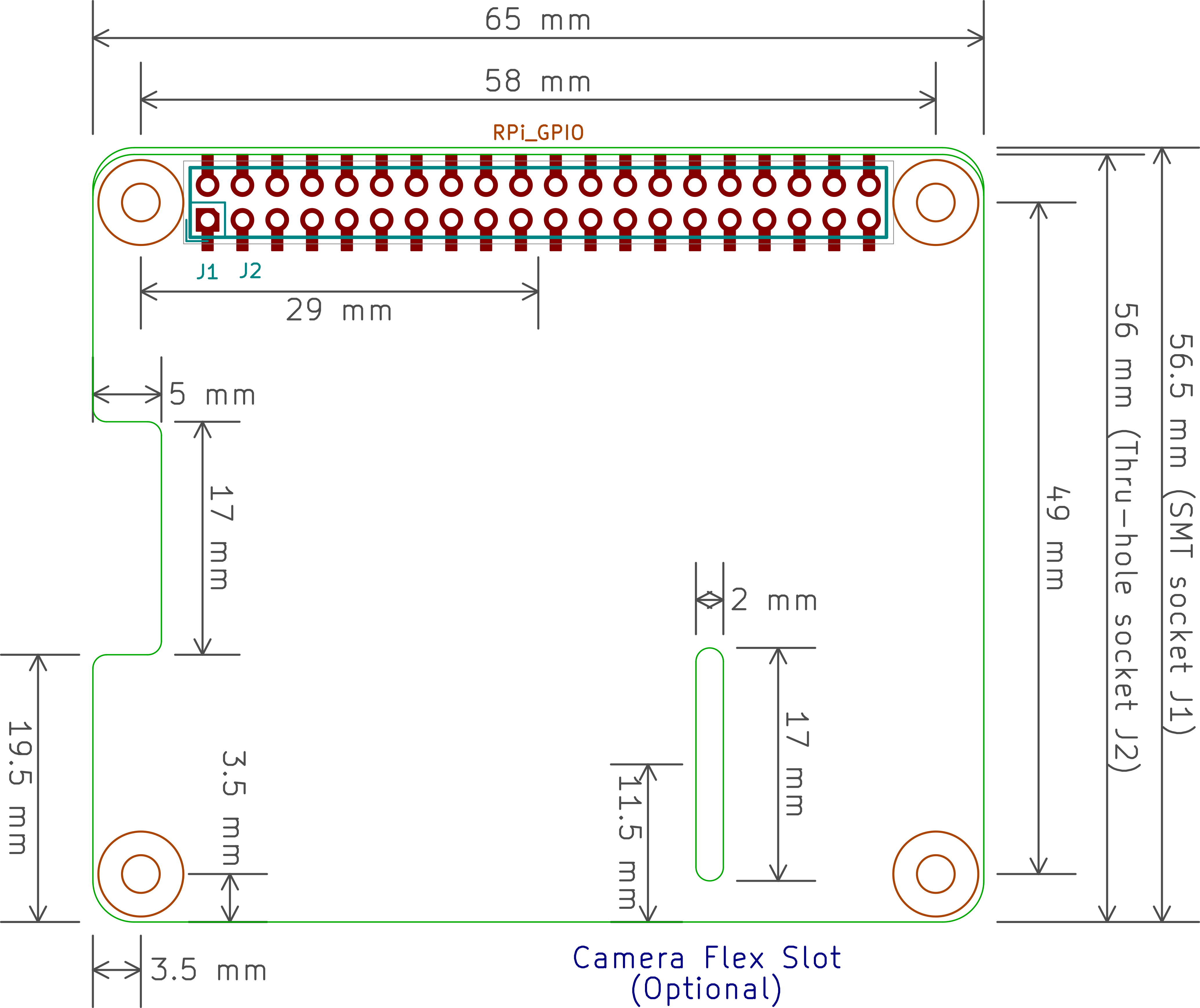
To use the Raspberry Pi Hat template with the through-hole connector, do the following:
To use the Raspberry Pi Hat template with the SMD connector, do the following:
(c)2015 XESS Corp.
| Qty | Value | Footprint | References |
|---|---|---|---|
| 20 | ZENER | Diodes_SMD:SOD-523 | D1, D2, D4, D10, D11, D12, D13, D14, D16, D17, D18, D19, D20, D21, D22, D23 +4 |
| 19 | C | Capacitors_SMD:C_0603 | C1, C2, C4, C5, C6, C10, C11, C12, C14, C15, C16, C17, C18, C19, C20, C21 +3 |
| 9 | 10k | Resistors_SMD:R_0603 | R2, R25, R26, R27, R28, R29, R30, R31, R32 |
| 8 | 1k | Resistors_SMD:R_0603 | R16, R17, R18, R19, R20, R21, R22, R23 |
| 8 | R | Resistors_ThroughHole:Resistor_Horizontal_RM10mm | R8, R9, R10, R11, R12, R13, R14, R15 |
| 3 | 100 | Resistors_SMD:R_0603 | R1, R3, R4 |
| 2 | DNM | Resistors_SMD:R_0603 | R33, R34 |
| 1 | 150 | Resistors_SMD:R_0603 | R6 |
| 1 | 180 | Resistors_SMD:R_0603 | R5 |
| 1 | 3.3V | Pin_Headers:Pin_Header_Straight_1x02 | P1 |
| 1 | ANA0 | Potentiometers:Potentiometer_WirePads | P8 |
| 1 | ANA1 | Potentiometers:Potentiometer_WirePads | P12 |
| 1 | ANA2 | Potentiometers:Potentiometer_WirePads | P16 |
| 1 | ANA3 | Potentiometers:Potentiometer_WirePads | P22 |
| 1 | ANA4 | Potentiometers:Potentiometer_WirePads | P9 |
| 1 | ANA5 | Potentiometers:Potentiometer_WirePads | P13 |
| 1 | ANA6 | Potentiometers:Potentiometer_WirePads | P17 |
| 1 | ANA7 | Potentiometers:Potentiometer_WirePads | P23 |
| 1 | BLUE TEST | LEDs:LED_0603 | D15 |
| 1 | CONN_01X05 | Pin_Headers:Pin_Header_Straight_1x05 | P27 |
| 1 | CP | Capacitors_ThroughHole:C_Radial_D5_L11_P2.5 | C13 |
| 1 | FUSE | Capacitors_SMD:C_1206_HandSoldering | F1 |
| 1 | GREEN PWR | LEDs:LED_0603 | D6 |
| 1 | I2C | Pin_Headers:Pin_Header_Straight_1x04 | P2 |
| 1 | LED0 | Pin_Headers:Pin_Header_Straight_1x02 | P7 |
| 1 | LED1 | Pin_Headers:Pin_Header_Straight_1x02 | P11 |
| 1 | LED2 | Pin_Headers:Pin_Header_Straight_1x02 | P15 |
| 1 | LED3 | Pin_Headers:Pin_Header_Straight_1x02 | P19 |
| 1 | LED4 | Pin_Headers:Pin_Header_Straight_1x02 | P21 |
| 1 | LED5 | Pin_Headers:Pin_Header_Straight_1x02 | P24 |
| 1 | LED6 | Pin_Headers:Pin_Header_Straight_1x02 | P25 |
| 1 | LED7 | Pin_Headers:Pin_Header_Straight_1x02 | P26 |
| 1 | MAX7313 | Housings_SSOP:SSOP-24_3.9x8.7mm_Pitch0.635mm | U1 |
| 1 | MCP3008 | Housings_SOIC:SOIC-16_3.9x9.9mm_Pitch1.27mm | U2 |
| 1 | Q_PNP_BEC | TO_SOT_Packages_SMD:SOT-23 | Q1 |
| 1 | R | Resistors_SMD:R_0603 | R7 |
| 1 | RED FAULT | LEDs:LED_0603 | D3 |
| 1 | SW0 | Pin_Headers:Pin_Header_Straight_1x02 | P3 |
| 1 | SW1 | Pin_Headers:Pin_Header_Straight_1x02 | P4 |
| 1 | SW2 | Pin_Headers:Pin_Header_Straight_1x02 | P5 |
| 1 | SW3 | Pin_Headers:Pin_Header_Straight_1x02 | P6 |
| 1 | SW4 | Pin_Headers:Pin_Header_Straight_1x02 | P10 |
| 1 | SW5 | Pin_Headers:Pin_Header_Straight_1x02 | P14 |
| 1 | SW6 | Pin_Headers:Pin_Header_Straight_1x02 | P18 |
| 1 | SW7 | Pin_Headers:Pin_Header_Straight_1x02 | P20 |

cosmoproject/cosmo-schematics
This is a project template for a Raspberry Pi B+ Hat.

eta-systems/MAX7313-breakout
Breakout Board for MAX7313 16 Channel Port Expander with 4 bit PWM


cyberboy666/recurBOY
a rpi0 video-instrument – created in collaboration with Guergana Tzatchkova

nekonaute/pogobot
Pogobot is an open-source open-hardware robotic platform for swarm robotics

cyberboy666/i_n_c_u_r
a r_e_c_u_r video sampler extension circuit - adding knobs, cv and serial midi control


IceyPlazza/EWB-EPA-Rainworks
26-27 EWB EPA Rainworks project; We're putting a sensor box in the ground!
It measures 148.6 × 24.1 mm and has 2 copper layers, 1.6 mm thick.
107 parts, built around the MAX7313AEG+ and MCP3008-I/P. The full list of its parts is on this page, with links to each part's symbol and footprint where PCBKit's library has them.
From the cosmoproject/cosmo-schematics repository on GitHub, at the commit this page was made from: the board is plank/plank.kicad_pcb. PCBKit opens the board in the browser, with nothing to install.
Its repository states no licence, so its author keeps all rights: ask cosmoproject before reusing the design.