4 layers194.5 × 188.6 mm
MyCpu
fortinsylvain/MyCpu
Home brew CPU Hardware with 1-bit ALU implementation using 74LSxx, a micro-code and assembler coded in C#.
162 parts18MIT

 CooperCollier/DigitalClock
A 12-hour digital clock created in logisim
DigitalClock is an open-source printed circuit board by CooperCollier, from the CooperCollier/DigitalClock repository on GitHub. It is a 2-layer board of 203.2 × 101.6 mm with 113 parts on 258 nets, routed with 2,301 tracks and 465 vias.
It is built around the 74LS74PC, 74LS86 and 74LS32SC, with the HDSP-7801, 74LS04PC and LM1117-5.0 among its other parts. Its parts include 54 ICs, 43 resistors, 7 capacitors, 3 transistors and 3 switches. It belongs with the lEDs and displays boards of this library.


A 12-hour digital clock made out of logic gates and flip-flops and implemented in Logisim.
This project incorporates the logisim 7-segment-display driver created here: https://github.com/marceloboeira/logisim-7-segment-display-driver.
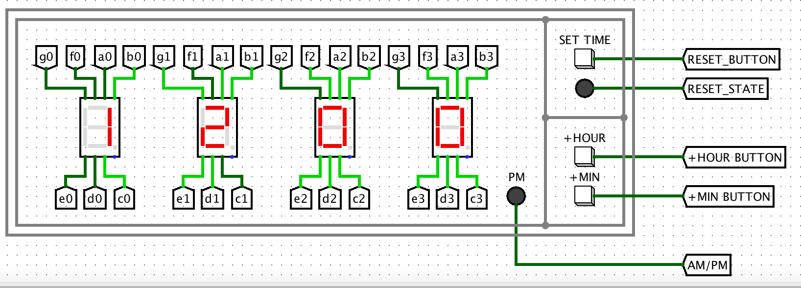
How to open this project:
1: clone this repository with git clone https://github.com/CooperCollier/DigitalClock --recursive. The recursive tag is necessary to include the 7-segment-display driver.
2: Open the file clock.circ in logisim.
3: Under the 'simulate' tab, set 'tick frequency' to 2Hz.
4: Under the 'simulate' tab, set 'ticks enabled' to true.
How to use the clock:
Press the SET TIME button to make the clock enter or exit the SET TIME state. When the clock is in the SET TIME state, the SET TIME LED will be turned on. When the clock enters the SET TIME state, the time is immediately reset to 12:00 AM.
Press the +MIN and +HOUR buttons to change the displayed time. These buttons are only active when the clock is in the SET TIME state.
| Qty | Value | Footprint | References |
|---|---|---|---|
| 33 | 1k | Resistor_THT:R_Axial_DIN0207_L6.3mm_D2.5mm_P10.16mm_Horizontal | R10, R11, R13, R14, R15, R16, R17, R18, R19, R20, R21, R22, R23, R24, R25, R26 +17 |
| 16 | 74LS08 | Package_DIP:DIP-14_W7.62mm | U4, U16, U20, U21, U25, U28, U29, U32, U33, U37, U42, U43, U47, U48, U51, U53 |
| 16 | 74LS74 | Package_DIP:DIP-14_W7.62mm | U9, U13, U17, U22, U23, U24, U26, U27, U31, U34, U35, U38, U40, U41, U45, U46 |
| 7 | 10k | Resistor_THT:R_Axial_DIN0207_L6.3mm_D2.5mm_P10.16mm_Horizontal | R1, R2, R3, R4, R5, R6, R12 |
| 6 | 74LS86 | Package_DIP:DIP-14_W7.62mm | U18, U19, U30, U36, U39, U44 |
| 4 | 74LS32 | Package_DIP:DIP-14_W7.62mm | U5, U49, U50, U52 |
| 4 | 74LS47 | Package_DIP:DIP-16_W7.62mm | U1, U6, U8, U12 |
| 4 | HDSP-7801 | Display_7Segment:7SegmentLED_LTS6760_LTS6780 | U3, U7, U10, U14 |
| 3 | 100nF | Capacitor_THT:C_Disc_D5.0mm_W2.5mm_P5.00mm | C2, C3, C4 |
| 3 | 10uF | Capacitor_THT:CP_Radial_Tantal_D5.0mm_P5.00mm | C5, C6, C7 |
| 3 | 2N3904 | Package_TO_SOT_THT:TO-92_Inline | Q1, Q2, Q3 |
| 3 | SW_Push | Button_Switch_THT:SW_PUSH_6mm | SW1, SW2, SW3 |
| 2 | 74LS04 | Package_DIP:DIP-14_W7.62mm | U15, U54 |
| 2 | LED | LED_THT:LED_D3.0mm | D1, D2 |
| 1 | 10nF | Capacitor_THT:C_Disc_D5.0mm_W2.5mm_P5.00mm | C1 |
| 1 | 4.2k | Resistor_THT:R_Axial_DIN0207_L6.3mm_D2.5mm_P10.16mm_Horizontal | R7 |
| 1 | 70 | Resistor_THT:R_Axial_DIN0207_L6.3mm_D2.5mm_P10.16mm_Horizontal | R8 |
| 1 | 70k | Resistor_THT:R_Axial_DIN0207_L6.3mm_D2.5mm_P10.16mm_Horizontal | R9 |
| 1 | Battery | TerminalBlock_Phoenix:TerminalBlock_Phoenix_MKDS-1,5-2_1x02_P5.00mm_Horizontal | J1 |
| 1 | LM1117-5.0 | Package_TO_SOT_THT:TO-220-3_Vertical | U11 |
| 1 | NE555P | Package_DIP:DIP-8_W7.62mm | U2 |
It measures 203.2 × 101.6 mm and has 2 copper layers, 1.6 mm thick.
113 parts, built around the 74LS74PC, 74LS86, 74LS32SC and HDSP-7801. The full list of its parts is on this page, with links to each part's symbol and footprint where PCBKit's library has them.
From the CooperCollier/DigitalClock repository on GitHub, at the commit this page was made from: the board is DigitalClock/DigitalClock.kicad_pcb and its schematic DigitalClock/DigitalClock.kicad_sch. PCBKit opens the board in the browser, with nothing to install.
Its repository states no licence, so its author keeps all rights: ask CooperCollier before reusing the design.
fortinsylvain/MyCpu
Home brew CPU Hardware with 1-bit ALU implementation using 74LSxx, a micro-code and assembler coded in C#.


hkzlab/CGA_Redux
The Color Graphics Adapter Redux board is a more or less faithful clone of the original IBM CGA, based on the original schematics

clemarfolly/Microdigital-TK2000
Reprodução da PCB do TK-2000 da Microdigital, clone do Micro-Professor MPF-II

misterblack1/zenith_zt1
Information gathered on the Zenith ZT-1 / ZT-10 / ZT-11 and ZTX/ZT-x-A variants


ForgottenMachines/Entrex
The technologies documented here will include all like-kind systems manufactured by Nixdorf, Redifon, ROCC & Mera, all originally designed by Entrex Inc, Burlington, MA USA.