Skip to the content
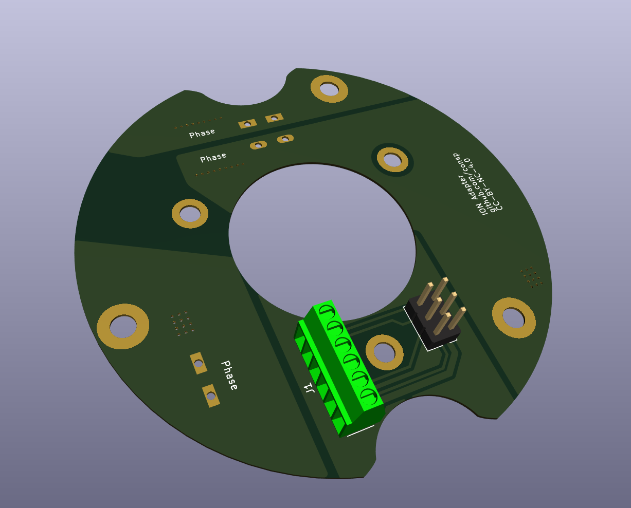
4 layers9.7 × 41 mm4l sram adapter, the printed circuit board in 3D

4l sram adapter

consp/pcbs1

PCB's I've designed which can be shared

Size
9.7 × 41 mm
Copper layers
4
Thickness
1.61 mm
Parts
4
Nets
32
Pads
68
Tracks, vias
128, 49
Pours
6
Routed
Yes
KiCad
KiCad 7 (file 20221018)
Created
11 Nov 2023
Updated
16 Jul 2026

Overview

4l sram adapter is an open-source printed circuit board by consp, from the consp/pcbs repository on GitHub. It is a 4-layer board of 9.7 × 41 mm with 4 parts on 32 nets, routed with 128 tracks and 49 vias.

Its parts include 2 connectors, 1 capacitor and 1 diode. It belongs with the interfaces and adapters boards of this library.

README

ion-xgt-adapter/README.md

Adapter for the (Sparta) ION XGT motors

The motor is a 20 magnet, 24 slot PMSM. It should be able to function with hall sensors but due to how it's configured you need to make sure the hall sensors are very precicely aligned.

[!WARNING]
The top magnet ring only has 10 magnets, you need some logic to fix this. The original board has 6 hall sensors to do this in an odd configuration. We choose a more simple one. The updated PCB with XOR gate and dual sensors is not yet finished.

You need some form of magic (logic or analogue) to offset the magnet difference. This can be done with interpretation but I chose the old fashioned digital logic aproach: Add another sensor per signal, offset by 90 degrees and XOR them to get a normal expected sample. There are more options logically but this is what I went with.

I forgot to take pictures before I sealed the motor again ... so no live images.

Features:

  • WAGO 238-402 connector, which you can get from the original board
  • Phoenix (or equivalen) 2.54mm screw terminals for the signal wires.
  • Bottom and top traces for the phases since the cheap PCB manufacturers use 1oz copper you need as much as you can get, but it should be more than enough for the 24A max rating of the WAGO connectors.

Advise to put together:

  • Disassemble motor, and remove old PCBs
  • Put new PCB in, make sure the contact is good with the phase screws. Middle screws can be ommitted, they are for tightening the fets to the heatsink but we do not need that but it's nice to have.
  • Pull your favourite 8/9 strand wire though the bearing hole. If you remove the bearing from the coverplate and only install that, it is very easy to access.
  • Put the phase leads into the connectors.
  • Put the bearing in place, grease/seal the cable in place to avoid basic water ingress and put the bearing in the correct spot.
  • Put on the cover plate and align the plate.
  • Test the motor's functionality.
  • It is possibley the hall phases are not exactly 60 degrees between transisions. You will need a motor controler which can handle that. They are consistent though.
  • Seal the cover plate with anti-water sealant and tighten it.

License

This work is licensed under CC BY-NC 4.0 (https://creativecommons.org/licenses/by-nc/4.0/)

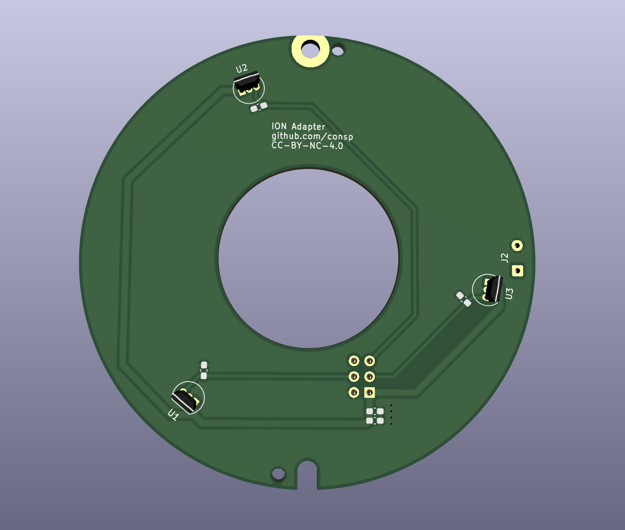
board

Final version

bottom top

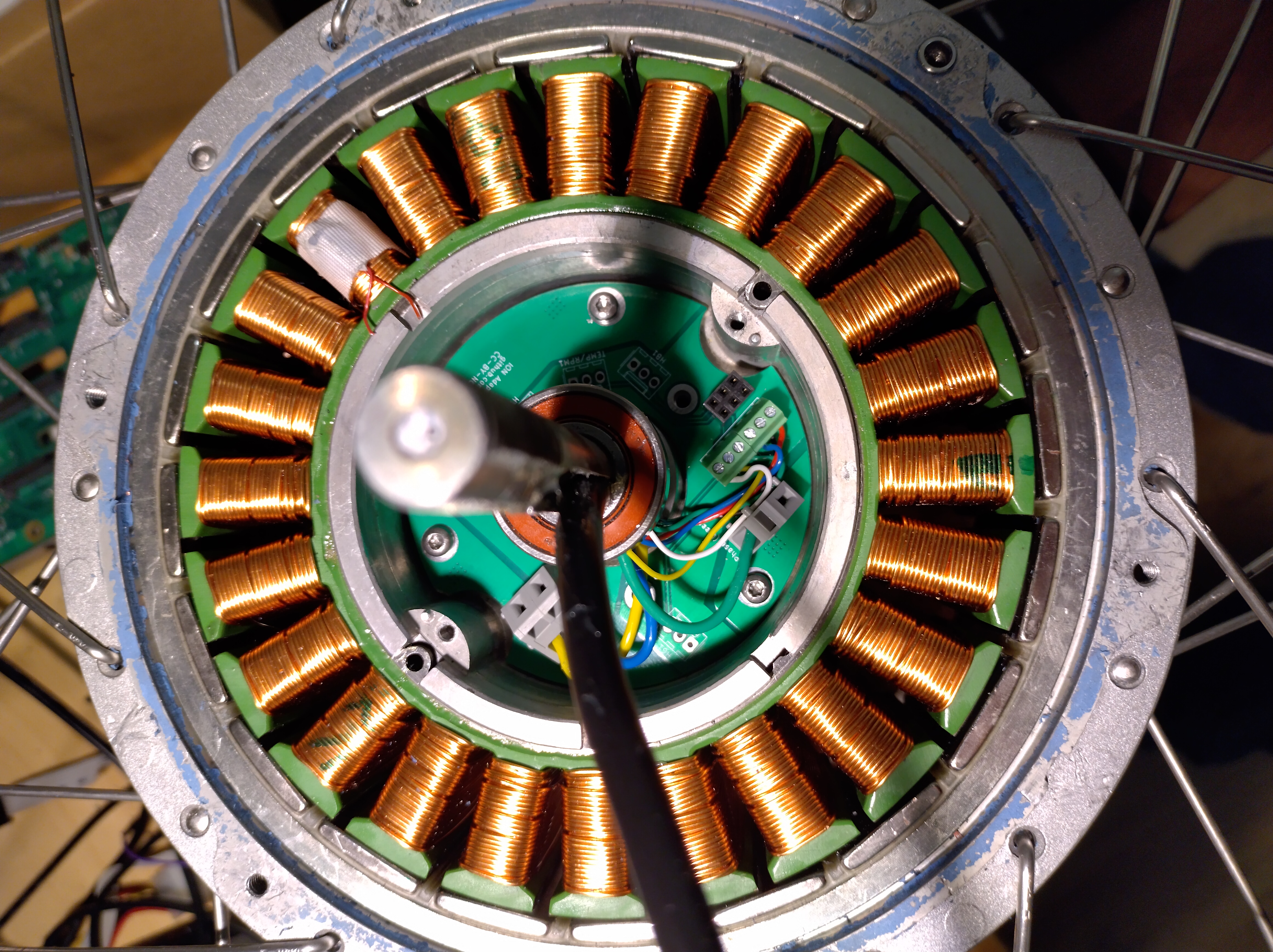
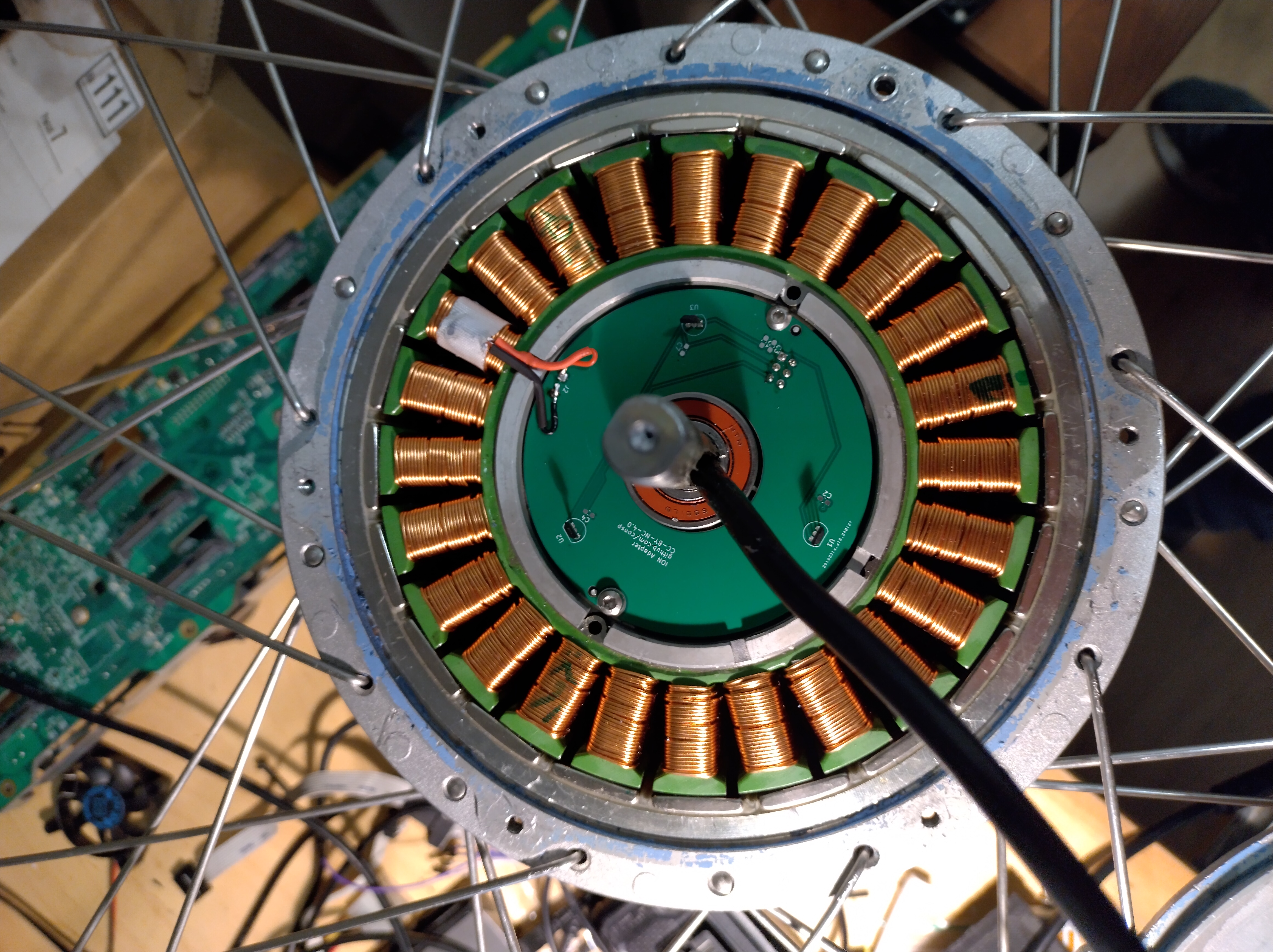
In the motor

bottom top

Parts

4
QtyValueFootprintReferences
110nFCapacitor_SMD:C_0805_2012Metric_Pad1.18x1.45mm_HandSolderC1
1628128_SRAM_PDIPsoj32:PDIP-32-SpecialJ2
1628128_SRAM_PDIPsoj32:SOJ-32J1
1DDiode_SMD:D_0603_1608Metric_Pad1.05x0.95mm_HandSolderD3

More from consp/pcbs

3
  • 2 layers16.6 × 75 mmIon hall top-120deg, the printed circuit board in 3D

    Ion hall top-120deg

    consp/pcbs

    PCB's I've designed which can be shared

    13 parts1
  • 2 layers75 × 71.9 mmIon connector bottom, the printed circuit board in 3D

    Ion connector bottom

    consp/pcbs

    PCB's I've designed which can be shared

    10 parts1

Similar boards

  • 4 layers33.7 × 12.4 mmDisplay eval short, the printed circuit board in 3D

    Display eval short

    byrantech/laptop

    anyon_e, a highly integrated, high end, open source laptop. Attempt the impossible.

    4 parts4.3kMIT
  • 4 layers78 × 40 mmAdd on template, the printed circuit board in 3D

    Add on template

    dotstartech/wall-panel

    Wall mounted 4 inch touch display panel with CM4 inside

    4 parts445
  • 4 layers48.5 × 16.3 mmCoupler test, the printed circuit board in 3D

    Coupler test

    loxodes/vna

    Under development open hardware microwave vector network analyzer

    4 parts205
  • 4 layers27.5 × 25 mmVna amplifier, the printed circuit board in 3D

    Vna amplifier

    azonenberg/starshipraider

    Open hardware test equipment

    4 parts193BSD-3-Clause
  • 4 layers80 × 40 mmInit file, the printed circuit board in 3D

    Init file

    Hongcheng-Gao/EngiWorld

    Engiworld: What Can Frontier Agents Deliver in Professional Engineering Environments?

    4 parts52MIT
  • 4 layers44.5 × 59.5 mmBreadboard adapter, the printed circuit board in 3D

    Breadboard adapter

    OpenDevicePartnership/pico-de-gallo

    A tool for testing Embedded Rust drivers for discrete I2C/SPI components.

    4 parts21MIT
  • 4 layers28 × 17 mmJtag swd bridge, the printed circuit board in 3D

    Jtag swd bridge

    azonenberg/misc-devboards

    Miscellaneous prototype hardware that wasn't major enough to warrant a dedicated repo

    4 parts17BSD-3-Clause
  • 4 layers22 × 30 mmM.2 usd, the printed circuit board in 3D

    M.2 usd

    martonmiklos/m.2_microsd

    M.2 E key to micro SD adapter CAD files

    4 parts17

Questions

How big is the 4l sram adapter PCB?

It measures 9.7 × 41 mm and has 4 copper layers, 1.61 mm thick.

What parts does the 4l sram adapter use?

4 parts. The full list of its parts is on this page, with links to each part's symbol and footprint where PCBKit's library has them.

Where can I download the 4l sram adapter KiCad files?

From the consp/pcbs repository on GitHub, at the commit this page was made from: the board is 486sram-adapter/4l sram adapter.kicad_pcb and its schematic 486sram-adapter/4l sram adapter.kicad_sch. PCBKit opens the board in the browser, with nothing to install.

Can I use the 4l sram adapter design in my own project?

Its repository states no licence, so its author keeps all rights: ask consp before reusing the design.