2 layers85.6 × 51.6 mm

 consp/pcbs1
PCB's I've designed which can be shared
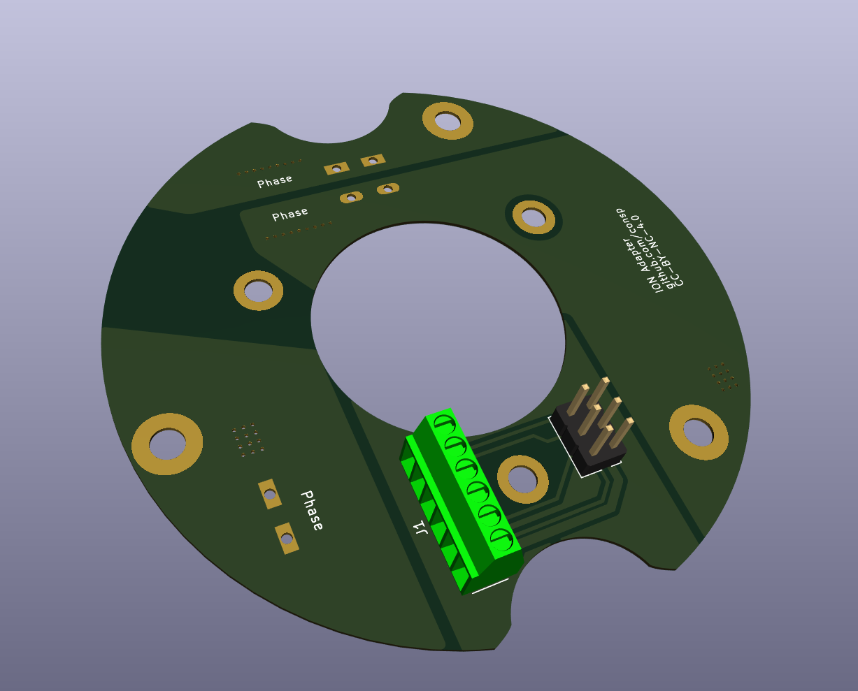
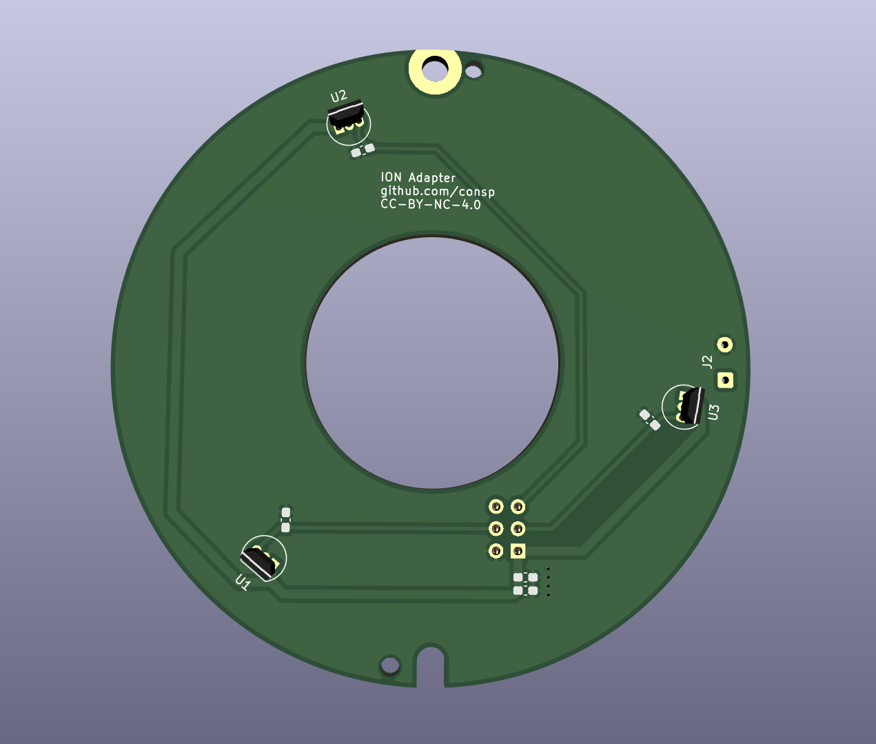
Ion hall top-120deg is an open-source printed circuit board by consp, from the consp/pcbs repository on GitHub. It is a 2-layer board of 16.6 × 75 mm with 13 parts on 7 nets, routed with 29 tracks and 4 vias.
Its parts include 5 capacitors, 3 ICs and 2 connectors.
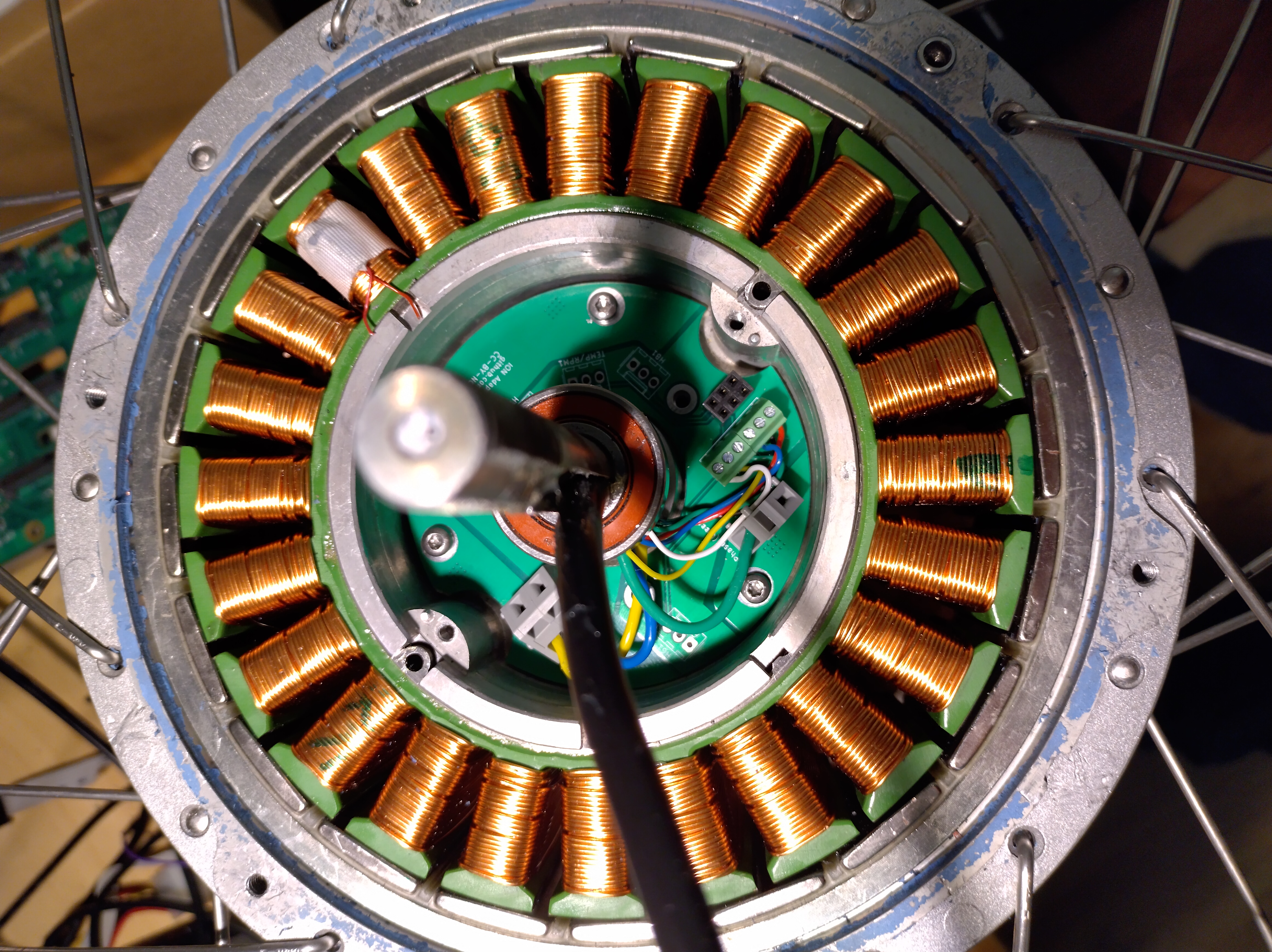
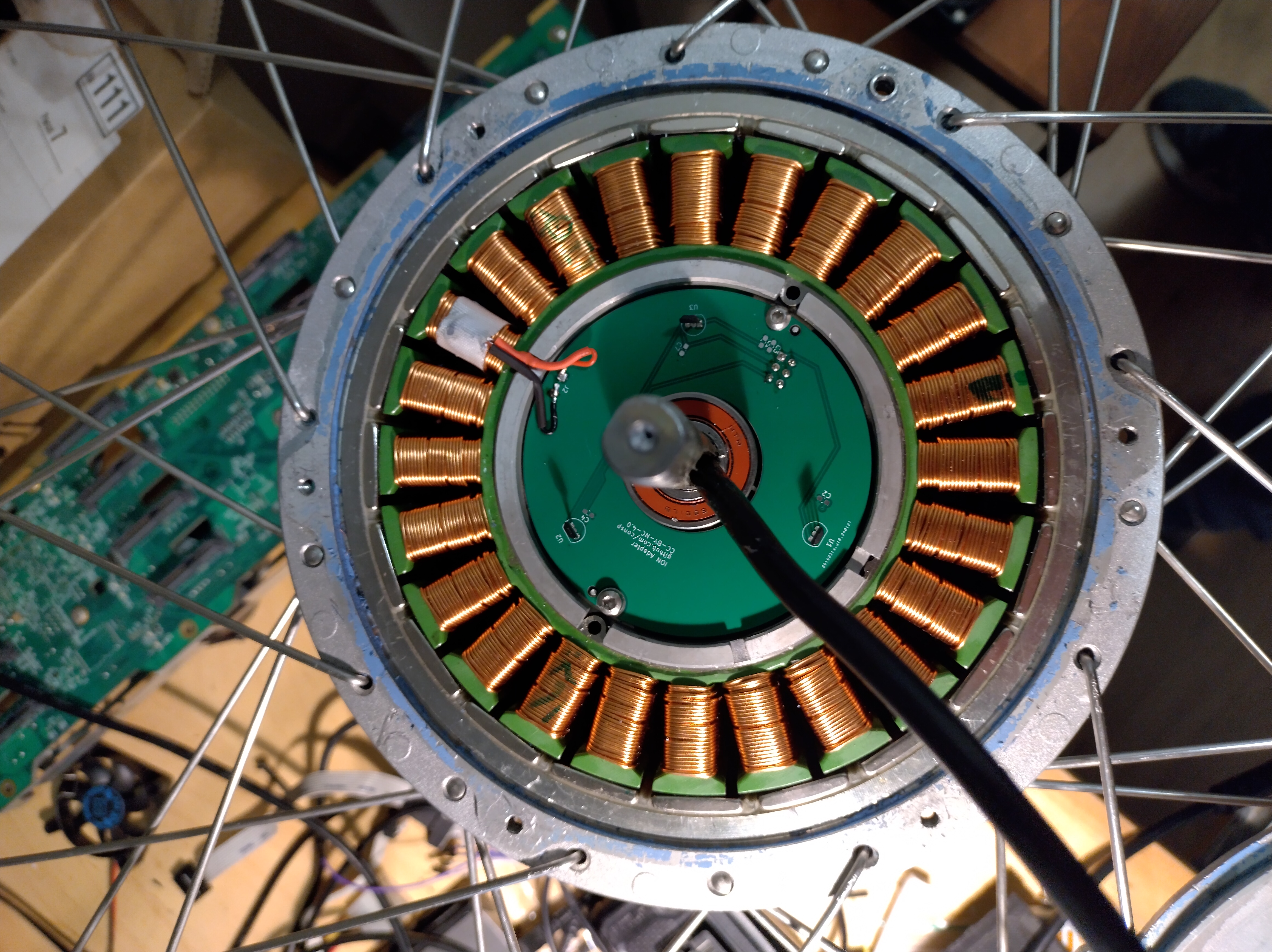
The motor is a 20 magnet, 24 slot PMSM. It should be able to function with hall sensors but due to how it's configured you need to make sure the hall sensors are very precicely aligned.
[!WARNING]
The top magnet ring only has 10 magnets, you need some logic to fix this. The original board has 6 hall sensors to do this in an odd configuration. We choose a more simple one. The updated PCB with XOR gate and dual sensors is not yet finished.
You need some form of magic (logic or analogue) to offset the magnet difference. This can be done with interpretation but I chose the old fashioned digital logic aproach: Add another sensor per signal, offset by 90 degrees and XOR them to get a normal expected sample. There are more options logically but this is what I went with.
I forgot to take pictures before I sealed the motor again ... so no live images.
Features:
Advise to put together:
This work is licensed under CC BY-NC 4.0 (https://creativecommons.org/licenses/by-nc/4.0/)
| Qty | Value | Footprint | References |
|---|---|---|---|
| 4 | ~ | Capacitor_SMD:C_0603_1608Metric_Pad1.08x0.95mm_HandSolder | C1, C2, C3, C4 |
| 3 | ~ | Library:TO-92_Inline_30mm_offset | U1, U2, U3 |
| 2 | MountingHole | MountingHole:MountingHole_2.1mm | H1, H2 |
| 1 | 10nF | Capacitor_SMD:C_0603_1608Metric_Pad1.08x0.95mm_HandSolder | C7 |
| 1 | Conn_01x02 | Connector_Wire:SolderWire-0.25sqmm_1x02_P4.2mm_D0.65mm_OD1.7mm | J2 |
| 1 | Conn_02x03_Odd_Even | Connector_PinSocket_2.54mm:PinSocket_2x03_P2.54mm_Vertical | J1 |
| 1 | MountingHole_Pad | MountingHole:MountingHole_3.2mm_M3_Pad | H3 |


samyk/magspoof
A portable device that can spoof/emulate any magnetic stripe, credit card or hotel card "wirelessly", even on standard magstripe (non-NFC/RFID) readers.

fossasia/pslab-scripts
Pocket Science Lab - Scripts for Sensor Experiments


willem-pennings/balancing-cube
A cube that balances itself in a corner or edge using reaction wheels

VoronDesign/Voron-Hardware
Cool Hardware designed by the Voron Design group

hoglet67/RGBtoHDMI
Bare-metal Raspberry Pi project that provides pixel-perfect sampling of Retro Computer RGB/YUV video and conversion to HDMI
It measures 16.6 × 75 mm and has 2 copper layers, 1.6 mm thick.
13 parts. The full list of its parts is on this page, with links to each part's symbol and footprint where PCBKit's library has them.
From the consp/pcbs repository on GitHub, at the commit this page was made from: the board is ion-xgt-adapter/ion-hall-top-120deg.kicad_pcb and its schematic 486sram-adapter/4l sram adapter.kicad_sch. PCBKit opens the board in the browser, with nothing to install.
Its repository states no licence, so its author keeps all rights: ask consp before reusing the design.