
2 layers81.1 × 69 mm
BancoDePruebas
LaboratorioGluon/Rc-Test-Bench
Projecto para caracterización de motores RC.
55 partsGPL-3.0

 Colahall/tiny85fancontrol10
ATTiny85 Fan Controler
Tiny85fancontrol is an open-source printed circuit board by Colahall, from the Colahall/tiny85fancontrol repository on GitHub, published under the MIT licence. It is a 2-layer board of 25.4 × 25.4 mm with 11 parts on 11 nets, routed with 30 tracks and 0 vias.
It is built around the ATTINY85-20PU, DS18B20 and IRF3808PBF. Its parts include 3 resistors, 2 ICs, 2 connectors, 1 capacitor and 1 diode. It belongs with the AVR (ATmega, ATtiny) boards of this library.




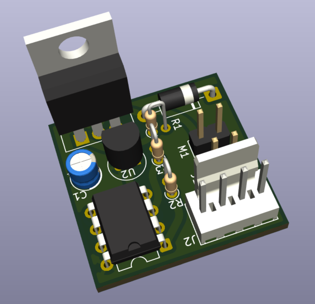
A temperature-controlled fan system powered by an ATtiny85 and a DS18B20 temperature sensor.
⚠️ This project is a work in progress and may not yet be suitable for all use cases.
You'll need the following components:
Refer to the Bill of Materials (BOM) for part numbers and quantities.
sudo apt-get install build-essential avrdude gcc-avr binutils-avr avr-libc gitsudo dnf install avrdude avr-gcc avr-libc gitbrew tap osx-cross/avr
brew install avr-gcc avrdude gitUse WSL and follow the Ubuntu instructions inside your Linux environment.
To build this project, run make in the root directory of the project.
cd /path/to/project/

make        # Builds the binary
make fuse   # Fuses the chip with the configuration
make flash # Uploads to the ATtiny85 via USBtinyISPThis project is working well for my needs, but there are still some things that could be improved.
Feel free to open an issue or submit a pull request if you have any ideas for improvements!
Pull requests and issues are welcome! If you’ve got a feature idea or fix, feel free to:
Please follow the existing code style and structure where possible.
This project is licensed under the MIT License.
| Qty | Value | Footprint | References |
|---|---|---|---|
| 1 | 0.1u | Capacitor_THT:CP_Radial_D4.0mm_P2.00mm | C1 |
| 1 | 100R | Resistor_THT:R_Axial_DIN0204_L3.6mm_D1.6mm_P1.90mm_Vertical | R2 |
| 1 | 10k | Resistor_THT:R_Axial_DIN0204_L3.6mm_D1.6mm_P1.90mm_Vertical | R1 |
| 1 | 1N4001 | Diode_THT:D_DO-41_SOD81_P10.16mm_Horizontal | D1 |
| 1 | 4.7k | Resistor_THT:R_Axial_DIN0204_L3.6mm_D1.6mm_P1.90mm_Vertical | R3 |
| 1 | ATtiny85-20P | Package_DIP:DIP-8_W7.62mm | U1 |
| 1 | DS18B20 | Package_TO_SOT_THT:TO-92_Inline | U2 |
| 1 | Fan | Connector_PinHeader_2.54mm:PinHeader_1x02_P2.54mm_Vertical | M1 |
| 1 | IRF3808 | Package_TO_SOT_THT:TO-220-3_Vertical | Q1 |
| 1 | Molex | Connector_Molex:Molex_KK-254_AE-6410-04A_1x04_P2.54mm_Vertical | J2 |
| 1 | UART_DBG | Connector_PinHeader_2.54mm:PinHeader_1x02_P2.54mm_Vertical | J1 |
LaboratorioGluon/Rc-Test-Bench
Projecto para caracterización de motores RC.

alxsrdrg/Water-saving-module
This is the data gatherer for a bigger project that will collect ambient data to save water while watering plants.


bwack/C64-Switchless-Multi-Kernal-27C256-adapter
Kernal switcher for the C64/C64C/C128

plusvic/simplebus2-intercom
General description of the Simplebus2 protocol used by some Comelit's intercoms. Hardware for retransmitting Simplebus2 messages over UART.

osmocom/osmocom-analog
Software Implementation of analog cellular telephony systems like NMT, TACS, IMTS, A/B/C-Netz; mirror of https://gitea.osmocom.org/cellular-infrastructure/osmocom-analog

strickyak/jerboa-attiny85-mod-synth
Modular Synthesizer using an ATtiny85 chip for each module.

It measures 25.4 × 25.4 mm and has 2 copper layers, 1.6 mm thick.
11 parts, built around the ATTINY85-20PU, DS18B20 and IRF3808PBF. The full list of its parts is on this page, with links to each part's symbol and footprint where PCBKit's library has them.
From the Colahall/tiny85fancontrol repository on GitHub, at the commit this page was made from: the board is schematic/tiny85fancontrol/tiny85fancontrol.kicad_pcb and its schematic schematic/tiny85fancontrol/tiny85fancontrol.kicad_sch. PCBKit opens the board in the browser, with nothing to install.
Its repository publishes it under the MIT licence: you may reuse it on that licence's terms (keep the author's notice, and for a copyleft licence share your changes alike).