2 layers66.1 × 70.8 mm

 codingcatgirl/split-flap-fae-pcb31
Alternative drop-in replacement PCB for David Kingsman's split-flap display
Splitflappcb is an open-source printed circuit board by codingcatgirl, from the codingcatgirl/split-flap-fae-pcb repository on GitHub, published under the Apache-2.0 licence. It is a 2-layer board of 40 × 80 mm with 46 parts on 64 nets, routed with 365 tracks and 98 vias.
It is built around the ATMEGA328P-AU, ESP-12E and TPS54302, with the ULN2003A, SS54 and WS2815E among its other parts. Its parts include 12 capacitors, 9 connectors, 8 resistors, 4 ICs and 3 diodes. It belongs with the lEDs and displays boards and the ESP8266 and AVR (ATmega, ATtiny) boards of this library.


This repository contains an alternative, improved, (near) drop-in replacement PCB for David Kingsman's Split-Flap Display.
Please note that due to some changes in pinout, you need to use evilscientress' improved fork of the firmware, which was specifically created along with this PCB.
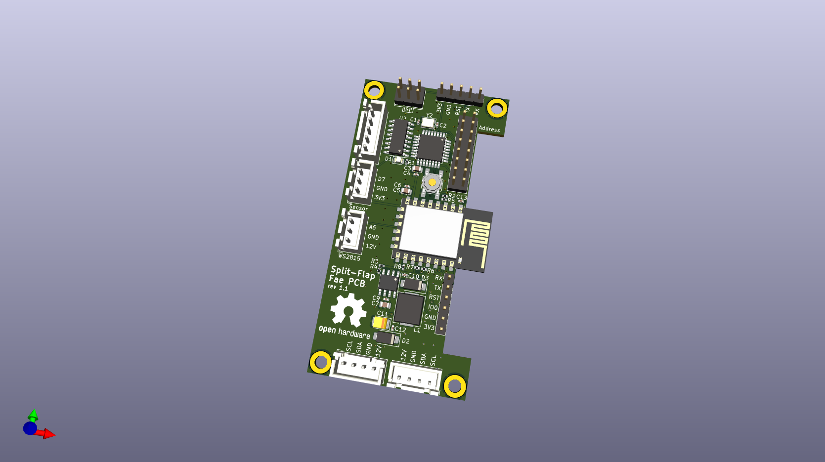
It provides the following Features:
fab folder for the PCB.fab folder for assembly.| Qty | Value | Footprint | References |
|---|---|---|---|
| 6 | 100n | Capacitor_SMD:C_0402_1005Metric | C4, C6, C9, C10, C12, C13 |
| 6 | 10k | Resistor_SMD:R_0402_1005Metric | R2, R3, R5, R6, R7, R8 |
| 4 | MountingHole_Pad | MountingHole:MountingHole_3.2mm_M3_DIN965_Pad | H1, H2, H3, H4 |
| 3 | 10uF | Capacitor_SMD:C_0805_2012Metric | C3, C5, C7 |
| 2 | 22pF | Capacitor_SMD:C_0402_1005Metric | C1, C2 |
| 2 | Conn_01x04_Pin | Connector_JST:JST_XH_B4B-XH-AM_1x04_P2.50mm_Vertical | J1, J2 |
| 2 | SS54 | Diode_SMD:D_SMA | D2, D3 |
| 1 | 16MHz | Crystal:Crystal_SMD_3225-4Pin_3.2x2.5mm | Y2 |
| 1 | 220 | Resistor_SMD:R_0402_1005Metric | R1 |
| 1 | 220uF | Capacitor_Tantalum_SMD:CP_EIA-3528-21_Kemet-B | C11 |
| 1 | 47uH | Inductor_SMD:L_Chilisin_BMRx00060630 | L1 |
| 1 | 5k9 | Resistor_SMD:R_0402_1005Metric | R4 |
| 1 | ATmega328P-A | Package_QFP:TQFP-32_7x7mm_P0.8mm | U3 |
| 1 | AVR-ISP-6 | Connector_PinHeader_2.54mm:PinHeader_2x03_P2.54mm_Vertical | J6 |
| 1 | AddressJumpers | Connector_PinHeader_2.54mm:PinHeader_2x08_P2.54mm_Vertical | J4 |
| 1 | Conn_01x05_Pin | Connector_JST:JST_XH_B5B-XH-AM_1x05_P2.50mm_Vertical | J3 |
| 1 | ESP-12E | RF_Module:ESP-12E | U4 |
| 1 | HallSensor | Connector_JST:JST_XH_B3B-XH-AM_1x03_P2.50mm_Vertical | J5 |
| 1 | LED | LED_SMD:LED_0805_2012Metric | D1 |
| 1 | RESET | Button_Switch_SMD:SW_SPST_SKQG_WithStem | SW1 |
| 1 | Serial-328P | Connector_PinHeader_2.54mm:PinHeader_1x05_P2.54mm_Vertical | J7 |
| 1 | Serial-ESP12E | Connector_PinHeader_2.54mm:PinHeader_1x06_P2.54mm_Vertical | J8 |
| 1 | TPS5430 | Package_SO:SOIC-8-1EP_3.9x4.9mm_P1.27mm_EP2.514x3.2mm_ThermalVias | U1 |
| 1 | ULN2003A | Package_SO:SOIC-16_3.9x9.9mm_P1.27mm | U2 |
| 1 | WS2815 | Connector_JST:JST_XH_B3B-XH-AM_1x03_P2.50mm_Vertical | J9 |
The 43 most common of 46 parts.
It measures 40 × 80 mm and has 2 copper layers, 1.6 mm thick.
46 parts, built around the ATMEGA328P-AU, ESP-12E, TPS54302 and ULN2003A. The full list of its parts is on this page, with links to each part's symbol and footprint where PCBKit's library has them.
From the codingcatgirl/split-flap-fae-pcb repository on GitHub, at the commit this page was made from: the board is splitflappcb.kicad_pcb and its schematic splitflappcb.kicad_sch. PCBKit opens the board in the browser, with nothing to install.
Its repository publishes it under the Apache-2.0 licence: you may reuse it on that licence's terms (keep the author's notice, and for a copyleft licence share your changes alike).

Joseph-Ladino/stm32-led-controller
Custom STM32 based led strip controller targeting WS2815. Features include Ethernet, WiFi, USB-C (USB 2.0) and a load switch for disconnecting the strip's power

MrRooby/Maszyna-W-ESP32
ESP32 based project with addressable LED displays, simulating basic CPU architecture with website Websocket connectivity for real time visualization

SurrealityLabs/smart-led-corners
For making smart LED strips turn 90 degrees

VarunAPatil/Wall-E-2027-Board-Design
The SRA board brings the control, sensing, display, power, and motor interfaces for a small mobile robot onto one development board.

AllYarnsAreBeautiful/ayab-hardware
Contains the schematics and layouts for the AYAB Arduino shield

MSzalawiga/Payload-Control-Board
Science Payload Control Board for Queen's Space Engineering Team

euphi/ESP-LEDCtrl
LED Strip Controller (2x RGB, 1 White) with ESP8266 Homie (MQTT)