4 layers32.5 × 29.3 mm
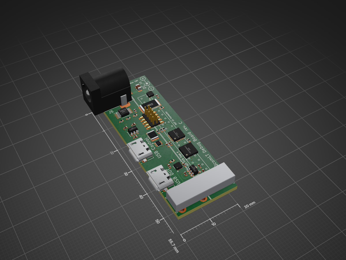
 CodeLinaro-mirror/qcomlt_debugboard
96boards specifications compliant Mezzanine used to control the DC Input, USB VBUS, PWR/RST buttons and Debug UART via a single USB2.0 CDC interface.
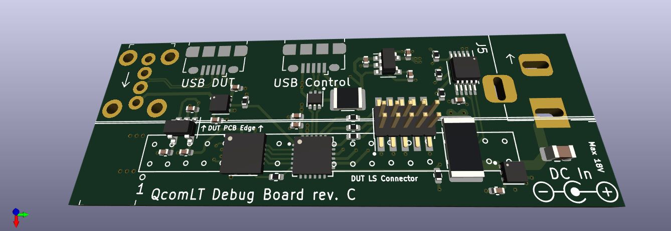
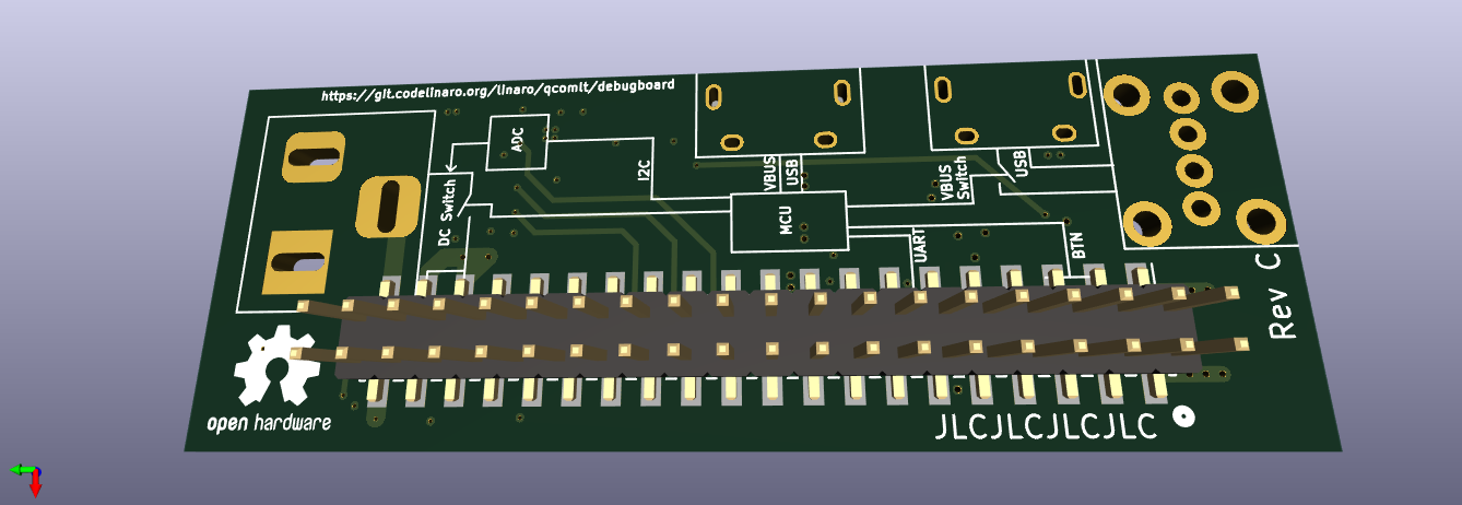
Qcomlt debugboard is an open-source printed circuit board by CodeLinaro-mirror, from the CodeLinaro-mirror/qcomlt_debugboard repository on GitHub, published under the CERN-OHL-P-2.0 licence. It is a 4-layer board of 20 × 55.7 mm with 40 parts on 90 nets, routed with 350 tracks and 69 vias.
It is built around the ATSAMD11D14A-MU, TPS22810DRV and TPS79318DBVR-TP, with the TPS79333DBVR-TP, TXS0104ERGYR and USBLC6-2P6 among its other parts. Its parts include 13 capacitors, 10 resistors, 8 ICs and 6 connectors. It belongs with the SAM D and SAM boards of this library.


96boards specifications compliant Mezzanine used to control the DC Input, USB VBUS, PWR/RST buttons and Debug UART via a single USB2.0 CDC interface.
The current design has been saved from KiCad 7.
PDF Schematics are available [here](QcomLT_DebugBoard Schematics.pdf).
Firmware is available at linaro/qcomlt/debugboard-fw, Gerber zip file in gerber/ directory and assembly files (BOM and positions) in assembly/ directory.
CERN-OHL-P (CERN Open Hardware Licence v2 permissive)
| Qty | Value | Footprint | References |
|---|---|---|---|
| 5 | 4k7 | Resistor_SMD:R_0402_1005Metric | R7, R8, R10, R12, R13 |
| 3 | 0.1uF | Capacitor_SMD:C_0402_1005Metric | C1, C4, C7 |
| 3 | 22 | Resistor_SMD:R_0402_1005Metric | R6, R9, R11 |
| 2 | 0.01uF | Capacitor_SMD:C_0402_1005Metric | C2, C5 |
| 2 | 10nF | Capacitor_SMD:C_0402_1005Metric | C11, C13 |
| 2 | 10uF | Capacitor_SMD:C_0402_1005Metric | C3, C6 |
| 2 | Micro-USB | Connector_USB:USB_Micro-B_Amphenol_10118194_Horizontal | J1, J4 |
| 2 | TPS22810DRV | Package_SON:WSON-6-1EP_2x2mm_P0.65mm_EP1x1.6mm | U7, U8 |
| 1 | 0.02 | Resistor_SMD:R_2512_6332Metric | R5 |
| 1 | 100@100MHz | Resistor_SMD:R_1210_3225Metric | FB1 |
| 1 | 100nF | Capacitor_SMD:C_0402_1005Metric | C9 |
| 1 | 1k | Resistor_SMD:R_0402_1005Metric | R1 |
| 1 | 1uF | Capacitor_SMD:C_0805_2012Metric | C12 |
| 1 | 1uF | Capacitor_SMD:C_0402_1005Metric | C10 |
| 1 | 4.7uF | Capacitor_SMD:C_0402_1005Metric | C8 |
| 1 | 73725-0110BLF | digikey-footprints:USB_A_Female_Vertical_RA_73725-0110BLF | J7 |
| 1 | ATSAMD11D14A-M | Package_DFN_QFN:QFN-24-1EP_4x4mm_P0.5mm_EP2.6x2.6mm | U4 |
| 1 | Barrel_Jack_Switch | Connector_BarrelJack:BarrelJack_Horizontal | J5 |
| 1 | INA233 | Package_SO:VSSOP-10_3x3mm_P0.5mm | U5 |
| 1 | LS1 | Mouser Footprints:PinHeader_2x20_P2.00mm_Vertical_SMD_Mirrored | J2 |
| 1 | SWD | Connector_PinHeader_1.27mm:PinHeader_2x05_P1.27mm_Vertical_SMD | J3 |
| 1 | TPS79318DBVR | Package_TO_SOT_SMD:SOT-23-5 | U1 |
| 1 | TPS79333DBVR | Package_TO_SOT_SMD:SOT-23-5 | U3 |
| 1 | TXS0104ERGYR | Package_DFN_QFN:Texas_S-PVQFN-N14 | IC1 |
| 1 | USBLC6-2P6 | Package_TO_SOT_SMD:SOT-666 | U2 |
The 38 most common of 40 parts.
It measures 20 × 55.7 mm and has 4 copper layers, 1.6 mm thick.
40 parts, built around the ATSAMD11D14A-MU, TPS22810DRV, TPS79318DBVR-TP and TPS79333DBVR-TP. The full list of its parts is on this page, with links to each part's symbol and footprint where PCBKit's library has them.
From the CodeLinaro-mirror/qcomlt_debugboard repository on GitHub, at the commit this page was made from: the board is QcomLT_DebugBoard.kicad_pcb and its schematic QcomLT_DebugBoard.kicad_sch. PCBKit opens the board in the browser, with nothing to install.
Its repository publishes it under the CERN-OHL-P-2.0 licence: you may reuse it on that licence's terms (keep the author's notice, and for a copyleft licence share your changes alike).

martinribelotta/h7dragonman
STM32H7 board for industrial protocol bridge


