2 layers100 × 91 mm
Ummtss
cmos-droner/UM-TSS
This is a circuit by Jacob Watters (check the original block post), I just did the PCB-layout. In agreement with Jacob this is released here as open hardware.
74 parts4MIT

 cmos-droner/UM-TSS4
This is a circuit by Jacob Watters (check the original block post), I just did the PCB-layout. In agreement with Jacob this is released here as open hardware. Hopefully you enjoy the project and maybe you can even improve it!
Ummtss is an open-source printed circuit board by cmos-droner, from the cmos-droner/UM-TSS repository on GitHub, published under the MIT licence. It is a 2-layer board of 100 × 91 mm with 79 parts on 55 nets, routed with 702 tracks and 2 vias.
It is built around the TL072 and LM7805CT. Its parts include 26 capacitors, 23 resistors, 14 diodes, 6 ICs and 1 inductor.


This is a circuit by Jacob Watters (check the original block post), I just did the PCB-layout. In agreement with Jacob this is released here as open hardware. Hopefully you enjoy the project and maybe you can even improve it!
The circuit is based around a couple of 40106 hex-schmitt triggers. I removed the divider from Jacobs layout to make every sound triggerable by itself. The trigger ins are protected by clamping diodes.
PCB v1 has a couple of bugs (mainly because I used the wrong revision of Jacobs circuit duh). But the PCB can certainly be used to build a running circuit. Check the build guide for PCB rev. 1 here and the BOM
I already fixed most of the issued in the schematics for version 2. I hope that together we can make a second version of the PCB that runs more smooth!
I created a case which can be fabbed by a lasercutter. The SVG is available in the repo. The plans are for 3mm material! Here is an image of the first finished prototype (3mm colored HDF): 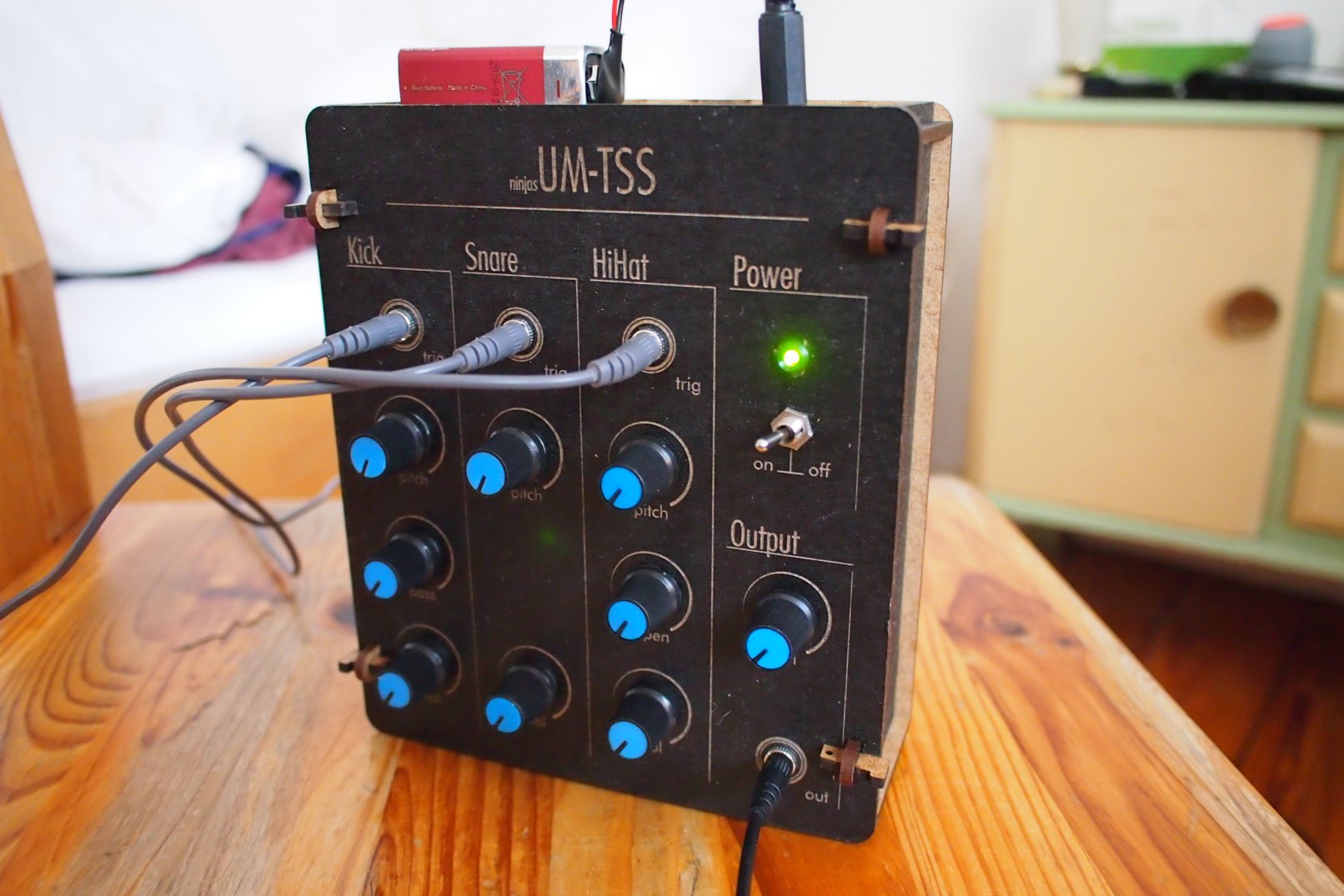
| Qty | Value | Footprint | References |
|---|---|---|---|
| 12 | 1N4148 | Diodes_ThroughHole:Diode_DO-35_SOD27_Horizontal_RM10 | D1, D4, D5, D6, D7, D8, D9, D10, D11, D12, D13, D14 |
| 8 | 1uF | Capacitors_ThroughHole:C_Radial_D5_L11_P2.5 | C4, C15, C16, C17, C21, C23, C25, C26 |
| 7 | 10k | synth-diy:Resistor_Horizontal_RM7mm_Wide | R4, R6, R10, R12, R15, R18, R19 |
| 4 | 100k | synth-diy:Resistor_Horizontal_RM7mm_Wide | R1, R2, R14, R20 |
| 4 | 100nF | synth-diy:C_Rect_L4.5_W2.5_P3 | C7, C8, C20, C22 |
| 4 | 1pin | Connect:1pin | H1, H2, H3, H4 |
| 4 | 40106 | Housings_DIP:DIP-14_W7.62mm_LongPads | U2, U3, U4, U5 |
| 4 | 47k | synth-diy:Resistor_Horizontal_RM7mm_Wide | R7, R11, R13, R23 |
| 3 | 33k | synth-diy:Resistor_Horizontal_RM7mm_Wide | R8, R17, R22 |
| 3 | 4.7k | synth-diy:Resistor_Horizontal_RM7mm_Wide | R3, R5, R21 |
| 3 | 8.2nF | synth-diy:C_Rect_L4.5_W2.5_P3 | C12, C13, C24 |
| 2 | 10nF | synth-diy:C_Rect_L4.5_W2.5_P3 | C14, C18 |
| 2 | 1N4004 | Diodes_ThroughHole:Diode_DO-41_SOD81_Horizontal_RM10 | D2, D3 |
| 1 | 1.3k | synth-diy:Resistor_Horizontal_RM7mm_Wide | R16 |
| 1 | 10uF | Capacitors_ThroughHole:C_Radial_D5_L11_P2.5 | C9 |
| 1 | 1M | synth-diy:Resistor_Horizontal_RM7mm_Wide | R9 |
| 1 | 220pF | synth-diy:C_Rect_L4.5_W2.5_P3 | C19 |
| 1 | 220uF | Capacitors_ThroughHole:C_Radial_D8_L11.5_P3.5 | C3 |
| 1 | 22uF | Capacitors_ThroughHole:C_Radial_D5_L11_P2 | C11 |
| 1 | 3.8uH | synth-diy:Resistor_Horizontal_RM7mm_Wide | L1 |
| 1 | 4.7uF | Capacitors_ThroughHole:C_Radial_D5_L11_P2.5 | C1 |
| 1 | 4.7uf | Capacitors_ThroughHole:C_Radial_D5_L11_P2.5 | C2 |
| 1 | 470nF | synth-diy:C_Rect_L4.5_W2.5_P3 | C5 |
| 1 | 47uF | Capacitors_ThroughHole:C_Radial_D6.3_L11.2_P2.5 | C6 |
| 1 | 82nF | synth-diy:C_Rect_L4.5_W2.5_P3 | C10 |
| 1 | Bassdrum | Pin_Headers:Pin_Header_Straight_1x12 | Bassdrum |
| 1 | HiHat | Pin_Headers:Pin_Header_Straight_1x12 | HiHat |
| 1 | LM7805CT | TO_SOT_Packages_THT:TO-92_Inline_Wide | U6 |
| 1 | Out | Pin_Headers:Pin_Header_Straight_1x05 | Out |
| 1 | PWR | Pin_Headers:Pin_Header_Straight_1x04 | Power |
| 1 | Snare | Pin_Headers:Pin_Header_Straight_1x10 | Snare |
| 1 | TL072 | Housings_DIP:DIP-8_W7.62mm_LongPads | U1 |
cmos-droner/UM-TSS
This is a circuit by Jacob Watters (check the original block post), I just did the PCB-layout. In agreement with Jacob this is released here as open hardware.

EleonoreMizo/pedalevite
Pédale Vite — DIY multi-FX pedalboard for guitar/bass/etc.

ThomasVDD/SmartSupply
SmartSupply is a digital battery powered lab powersupply. It is Arduino compatible and can be controlled via PC over USB.

DRWJSCHMIDT/T41
This is the repository for the officially released V10, V11, and V12 versions of the T41 Software Defined Transceiver hardware and kits.

balmerdx/BalmerDX_VNA
Vector Network Analyzer 10 KHz - 180 MHz


profdc9/ParanoiaBox
A standalone elliptic curve/AES file encryption and decryption device


It measures 100 × 91 mm and has 2 copper layers, 1.6 mm thick.
79 parts, built around the TL072 and LM7805CT. The full list of its parts is on this page, with links to each part's symbol and footprint where PCBKit's library has them.
From the cmos-droner/UM-TSS repository on GitHub, at the commit this page was made from: the board is schematics v1/ummtss.kicad_pcb. PCBKit opens the board in the browser, with nothing to install.
Its repository publishes it under the MIT licence: you may reuse it on that licence's terms (keep the author's notice, and for a copyleft licence share your changes alike).