4 layers50 × 75 mm
Overkill nRF
sneakylizard123-4/Overkill-nRF
A modular RF communication board designed for the Overkill system, built around the nRF24L01+ radio module instead of a bare RF IC + Amplifier.
80 parts
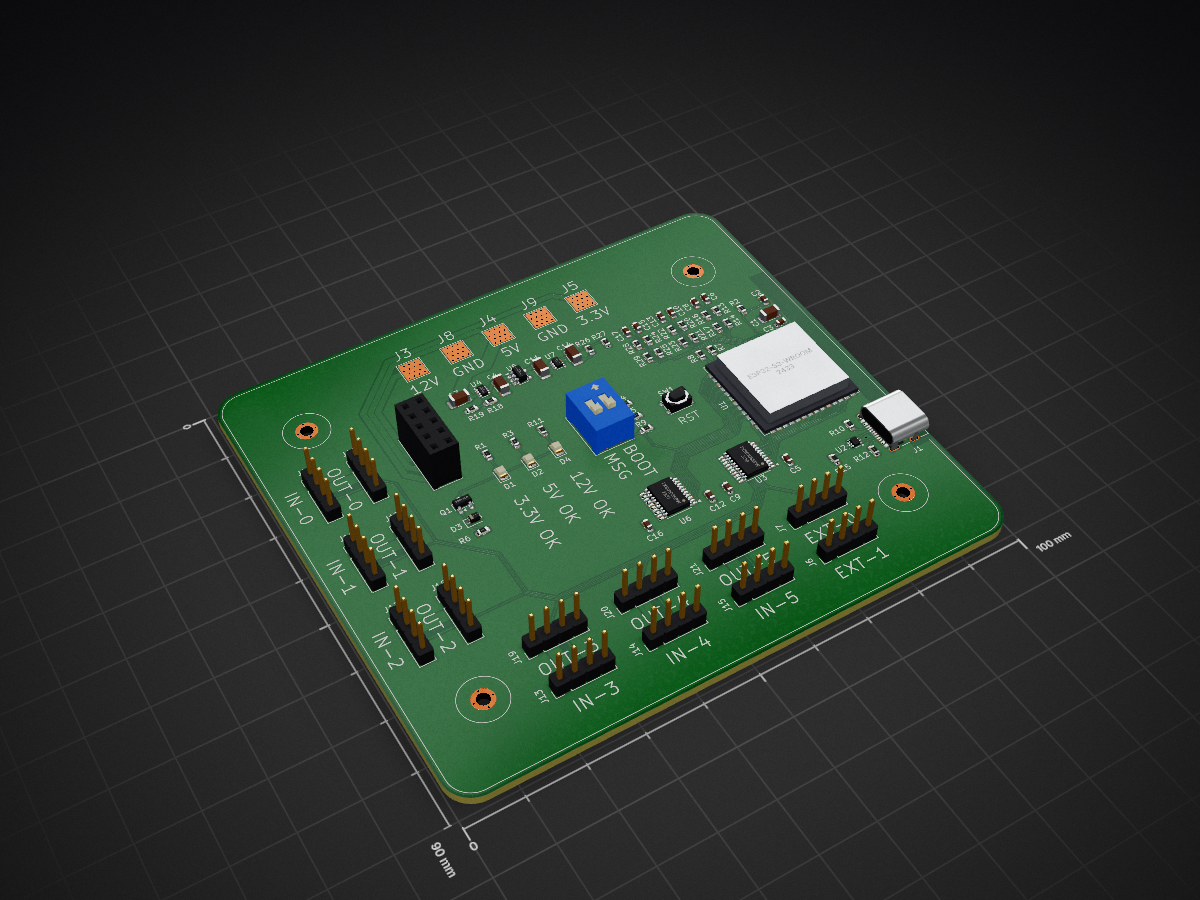
 Clamentos/FanCTRL
Fully programmable PWM fan controller
FanCTRL is an open-source printed circuit board by Clamentos, from the Clamentos/FanCTRL repository on GitHub, published under the CC-BY-SA-4.0 licence. It is a 6-layer board of 100 × 90 mm with 93 parts on 93 nets, routed with 614 tracks and 194 vias.
It is built around the ESP32-S3-WROOM-1U-N4, TPS2117DRL and TXS0108EPW, with the TLV75733PDBV, USBLC6-2P6 and AO3400A among its other parts. Its parts include 29 resistors, 26 connectors, 17 capacitors, 7 ICs and 4 diodes. It belongs with the ESP32 boards of this library.


A fully programmable PWM fan controller board for your desktop PC. It has 6 input channels and 8 output channels. The first 6 output channels take power from the inputs, while the last 2 take power from the provided 12V rail.
The board can be powered from the USB-C port (this option does not provide power to the last 2 fan output channels) or the 5 power pads (solder wires from a SATA cable).
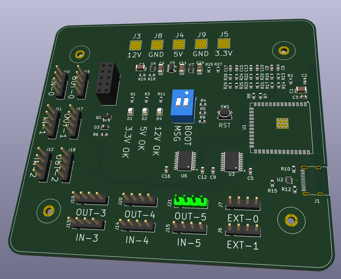
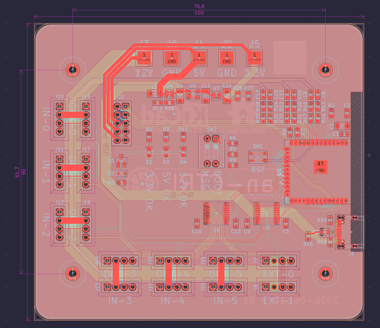
Board revision 1
Production files are provided in the releases section. For JLCPCB, the following files can be used:
Fan-CTRL_1.zip: ZIP containing the gerber files.bom.csv: The bill of materials CSV file.positions.csv: The component placement position CSV file.| Qty | Value | Footprint | References |
|---|---|---|---|
| 14 | Conn_01x04 | Connector_PinHeader_2.54mm:PinHeader_1x04_P2.54mm_Vertical | J6, J7, J10, J11, J12, J13, J14, J15, J16, J17, J18, J19, J20, J21 |
| 10 | Conn_01x01 | TestPoint:TestPoint_Pad_4.0x4.0mm | J3, J3, J4, J4, J5, J5, J8, J8, J9, J9 |
| 6 | 100K | Resistor_SMD:R_0603_1608Metric | R13, R16, R20, R22, R24, R28 |
| 6 | 100n | Capacitor_SMD:C_0603_1608Metric | C6, C8, C10, C13, C15, C17 |
| 6 | 1u | Capacitor_SMD:C_0603_1608Metric | C2, C3, C5, C9, C12, C16 |
| 6 | 200K | Resistor_SMD:R_0603_1608Metric | R14, R17, R21, R23, R25, R29 |
| 5 | 22K | Resistor_SMD:R_0603_1608Metric | R2, R18, R19, R26, R27 |
| 5 | 22u | Capacitor_SMD:C_1206_3216Metric | C1, C4, C7, C11, C14 |
| 4 | 47K | Resistor_SMD:R_0603_1608Metric | R3, R6, R9, R15 |
| 3 | LED_Filled | LED_SMD:LED_0805_2012Metric | D1, D2, D4 |
| 2 | 10K | Resistor_SMD:R_0603_1608Metric | R1, R11 |
| 2 | 1K | Resistor_SMD:R_0603_1608Metric | R4, R5 |
| 2 | 22 | Resistor_SMD:R_0603_1608Metric | R7, R8 |
| 2 | 5.1K | Resistor_SMD:R_0603_1608Metric | R10, R12 |
| 2 | TPS2117DRL | Package_TO_SOT_SMD:SOT-583-8 | U4, U7 |
| 2 | TXS0108EPW | Package_SO:TSSOP-20_4.4x6.5mm_P0.65mm | U3, U6 |
| 1 | AO3400A | Package_TO_SOT_SMD:SOT-23 | Q1 |
| 1 | BZT52C3V3S | Diode_SMD:D_SOD-323 | D3 |
| 1 | Conn_02x05_Counter_Clockwise | Connector_PinSocket_2.54mm:PinSocket_2x05_P2.54mm_Vertical | J2 |
| 1 | ESP32-S3-WROOM-1U | RF_Module:ESP32-S3-WROOM-1U | U1 |
| 1 | LOGO | LOGO | G*** |
| 1 | SW_DIP_x02 | Button_Switch_THT:SW_DIP_SPSTx02_Slide_9.78x7.26mm_W7.62mm_P2.54mm | SW2 |
| 1 | SW_Push | Button_Switch_SMD:SW_SPST_PTS810 | SW1 |
| 1 | TLV75733PDBV | Package_TO_SOT_SMD:SOT-23-5 | U5 |
| 1 | USBLC6-2P6 | Package_TO_SOT_SMD:SOT-666 | U2 |
| 1 | USB_C_Receptacle_USB2.0_16P | Connector_USB:USB_C_Receptacle_G-Switch_GT-USB-7010ASV | J1 |
The 87 most common of 93 parts.
It measures 100 × 90 mm and has 6 copper layers, 1.63 mm thick.
93 parts, built around the ESP32-S3-WROOM-1U-N4, TPS2117DRL, TXS0108EPW and TLV75733PDBV. The full list of its parts is on this page, with links to each part's symbol and footprint where PCBKit's library has them.
From the Clamentos/FanCTRL repository on GitHub, at the commit this page was made from: the board is fan_ctrl/fan_ctrl.kicad_pcb and its schematic fan_ctrl/fan_ctrl.kicad_sch. PCBKit opens the board in the browser, with nothing to install.
Its repository publishes it under the CC-BY-SA-4.0 licence: you may reuse it on that licence's terms (keep the author's notice, and for a copyleft licence share your changes alike).
sneakylizard123-4/Overkill-nRF
A modular RF communication board designed for the Overkill system, built around the nRF24L01+ radio module instead of a bare RF IC + Amplifier.

AndreiVladescu/LibrePLC32
The goal of the project is to create a compact, hackable, and well-documented PLC platform for industrial automation experiments, prototyping, education, and open hardware development.

htsong-lab/hardware
Hardware engineering portfolio: FPGA high-speed board, RoboMaster power electronics and smart-car projects.


mikesmitty/rp24-dcc-decoder
DIY DCC decoder for model railroad locomotives in an E24 form factor, powered by an RP2350 (Raspberry Pi Pico 2)
