4 layers40.3 × 22.9 mm
 ckflight/FMCW-RADAR59
Frequency Modulated Continuous Wave Radar hardware and software design files with 26 dBm output power covering around 250 m.
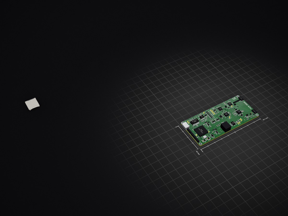
Radar v2 is an open-source printed circuit board by ckflight, from the ckflight/FMCW-RADAR repository on GitHub, published under the GPL-3.0 licence. It is a 4-layer board of 90.2 × 40 mm with 270 parts on 190 nets, routed with 1,727 tracks and 868 vias.
It is built around the PAT1220-C-6DB, HMC431LP4E and SKY65404-31, with the LT6232IGN, MAX1426EAI+ and TLV172ID among its other parts. Its parts include 116 capacitors, 67 resistors, 51 ICs, 11 diodes and 11 inductors. It belongs with the STM32 boards of this library.


Check the new design's Python files for better processing and analysis https://github.com/ckflight/FMCW_RADAR_2v2
New version of the hardware is available in the Radar 2 folder. For Radar 2 design, two separated boards in Radar MCU and Radar RF folders are brought together with several necessary improvements. I recommend using the second design since it is more reliable and tested. The reason behind two separate board was to change digital part of the board without changing the RF part of it. However, one united design performs better and have a better temperature cooling control which affect the overall perfomance significantly.
I have added a new Python script for plotting the radar data with Python Qt5 and Vispy plotting tool which uses GPU instead of CPU. Radar_Plot2.py is the source code. New code plots the time domain and frequency domain data together with scale and restart options. It has thread based approach between Vispy and Qt classes by using DataSource which allows us to manage more data. See first screenshot under Python Script Plots section below.
$$ Range(radar) = {\sqrt[4]{Pt * G^2 * \lambda^2 * \sigma \over Pmin * 4\pi^3}} $$
$$ Pthermal(watt) = {k * T * B * F} $$
$$ Pthermal(dBm) = {10\log_{10} {kT \over 1mW} + NF + 10\log_{10} BW} $$
$$ Pmin(dBm) = {Pthermal(dBm) + 20dB} $$
Radar, has an auto gain configuration with a digital potentiometer to control intermediate frequency (IF) signal gain at the last stage of the analog amplifier before sampling with ADC.
-40 dB / Decade Range Compensation Filter is implemented. Closer objects reflect more powerful RF signal which suppresses the signal of the objects at further distance. By amplifying the weaker signals and filtering the closer ones, each frequency band is adjusted to the same amplitude.
The IF signal is available at different stages of the amplifier and filter circuit for testing with other configurations.
The VCO range of the radar is from 5.5 to 6.1 GHz
Directional coupler has low insertion loss of 0.25 dB and 16 dB coupling.
ADF4158 Frequency Synthesizer is available due to the nonlinear characteristics of the VCO profile for accurate distance detection. ADF4158 can generate pulses with some gap between each sweep. During this gap samples are packed and buffered over USB.
STM32F4's DAC has a triangular waveform generation option and it can be used for VCO signal generation as well. Both option are available on board. Check schematic to populate necessary resistor values to use either mode.
SMA connector has 1 mm pad size, but the 50 Ohm transmission line is 0.342 mm wide. To prevent reflection, cutout is implemented beneath the SMA pad with CST Studio simulation which is also available at my repository https://github.com/ckflight/CST_ADS_MODELS_SIMULATIONS
PCB has 4 layers. 50 Ohm impedance microstrip transmission line is making 0.342mm trace width by using oshpark's stack-up below. Stack-up layer information can be found here: https://docs.oshpark.com/services/four-layer/
Main loop runs with a Finite State Machine (FSM) to control radar, which checks the condition of the start of the sweep and the gap. ADF4158 Muxout is generating a pulse according to the sweep condition. External interrupt tracks this pulse to move between FSM states.
Hardware is configured using Python script so the PC is in Host mode and controls everything. In this way, any hardware parameters can be changed without reflashing the firmware.
N number of samples are determined by sweep bandwidth rise time and the sampling frequency. For example:
Fs = 500.000 samples/sec and the sweep rise time is 1 millisecond (ms) for 200 MHz bandwidth. The system will pack 500 x 16 bit ADC samples and transfer 1000 x 8 bit ADC samples to Python script in 1 ms. Therefore, 1 MegaByte data is buffered to Host PC for 500 KHz sampling frequency in 1 second.
Python Script: I have uploaded an example record file along with python scripts where the peaks of the stationary objects can be seen.


| Qty | Value | Footprint | References |
|---|---|---|---|
| 41 | 100nF | Footprints:SMD_0402 | C1, C2, C3, C10, C20, C22, C23, C26, C27, C28, C29, C30, C100, C101, C109, C110 +25 |
| 18 | 1K | Footprints:SMD_0402 | R1, R10, R13, R20, R30, R39, R40, R46, R49, R56, R66, R67, R68, R69, R70, R71 +2 |
| 14 | Check_Point | Footprints:SolderPad_1_1.5mm_SMD_Circle | U3, U5, U10, U11, U14, U16, U24, U26, U34, U36, U39, U40, U41, U46 |
| 12 | 10uF | Footprints:SMD_0603 | C5, C12, C63, C64, C89, C91, C92, C95, C96, C97, C98, C99 |
| 11 | 10nF | Footprints:SMD_0402 | C57, C73, C74, C75, C77, C78, C93, C94, C102, C103, C107 |
| 10 | DNP | Footprints:SMD_0402 | C65, C71, R15, R23, R27, R28, R31, R72, R73, R75 |
| 9 | Led_Diode | Footprints:Diode_0603 | D3, D4, D5, D6, D7, D8, D9, D10, D11 |
| 8 | 10K | Footprints:SMD_0402 | R18, R21, R22, R41, R42, R61, R64, R65 |
| 8 | 10pF | Footprints:SMD_0402 | C39, C40, C52, C60, C61, C67, C68, C76 |
| 7 | 100pF | Footprints:SMD_0402 | C24, C25, C45, C47, C48, C53, C79 |
| 6 | 2.2uF | Footprints:SMD_0402 | C6, C11, C14, C15, C21, C69 |
| 5 | 0 | Footprints:SMD_0402 | R2, R3, R24, R33, R35 |
| 5 | 4.7K | Footprints:SMD_0402 | R17, R19, R36, R37, R63 |
| 5 | BLM18PG181SN1D | Footprints:SMD_0603 | L1, L4, L5, L8, L9 |
| 5 | Check_Point | Footprints:SolderPad_1_1.2mm_SMD_Circle | U47, U48, U49, U50, U51 |
| 5 | MITERED_BEND | Footprints:Mitered_Bend_0.33mm_90 | U23, U28, U42, U43, U44 |
| 4 | 100 | Footprints:SMD_0402 | R7, R8, R16, R76 |
| 4 | 1nF | Footprints:SMD_0402 | C72, C81, C82, C90 |
| 4 | 2.2uF | Footprints:SMD_0603 | C104, C105, C106, C108 |
| 4 | 22 | Footprints:SMD_0402 | R5, R6, R12, R74 |
| 4 | CONN_01X01 | Footprints:Mounting_3.2mm_Pad_Via | REF*, REF*, REF*, REF* |
| 3 | 16.7 | Footprints:SMD_0402 | R52, R77, R78 |
| 3 | 18pF | Footprints:SMD_0402 | C37, C38, C42 |
| 3 | 50 | Footprints:SMD_0402 | R25, R29, R59 |
| 2 | 130 | Footprints:SMD_0402 | R47, R48 |
| 2 | 15pF | Footprints:SMD_0402 | C16, C17 |
| 2 | 1uF | Footprints:SMD_0402 | C18, C19 |
| 2 | 2.2uH | Footprints:SMD_0603 | L2, L3 |
| 2 | 2.49K | Footprints:SMD_0402 | R9, R11 |
| 2 | 33pF | Footprints:SMD_0402 | C9, C13 |
| 2 | 4.7uH | Footprints:SMD_0805 | L10, L11 |
| 2 | 4.99K | Footprints:SMD_0402 | R50, R51 |
| 2 | 5400BL15B050E | Footprints:Balun_5400BL15B050E | U7, U13 |
| 2 | 910 | Footprints:SMD_0402 | R44, R45 |
| 2 | AP3211 | Footprints:SOT23_6 | U31, U32 |
| 2 | Diode_Schottky | Footprints:Diode_SDM2U30CSP_7 | D1, D2 |
| 2 | LDS3985 | Footprints:SOT23_5 | U33, U38 |
| 2 | LOGO | Footprints:Untitled | G***, G*** |
| 2 | PAT1220-C-6DB | Footprints:PAT1220_6dB | U19, U27 |
| 2 | SMA_Connector | Footprints:SMA_Connector | U22, U30 |
| 1 | 0 to 27 | Footprints:SMD_0402 | R57 |
| 1 | 0.5pF | Footprints:SMD_0402 | C83 |
| 1 | 0.6nH | Footprints:SMD_0402 | L7 |
| 1 | 1.8 | Footprints:SMD_0402 | R43 |
| 1 | 100K | Footprints:SMD_0402 | R38 |
| 1 | 14.7K | Footprints:SMD_0402 | R62 |
| 1 | 2.2nF | Footprints:SMD_0402 | C62 |
| 1 | 240 | Footprints:SMD_0402 | R32 |
| 1 | 30K | Footprints:SMD_0402 | R58 |
| 1 | 330nF | Footprints:SMD_0402 | C55 |
| 1 | 470pF | Footprints:SMD_0402 | C33 |
| 1 | 49.9 | Footprints:SMD_0402 | R14 |
| 1 | 5.49K | Footprints:SMD_0402 | R26 |
| 1 | 51.4K | Footprints:SMD_0402 | R60 |
| 1 | 8MHz | Footprints:Crystal_3.2x2.5mm | Y1 |
| 1 | ADC_Connector | Footprints:SolderPad_1_1.5mm_SMD_Circle | U25 |
| 1 | ADF4158 | Footprints:LFCSP24_4x4mm_P0.5mm_1EXP_2.5x2.5mm | U8 |
| 1 | ADL5801 | Footprints:LFCSP24_4x4mm_P0.5mm_1EXP_2.5x2.5mm | U9 |
| 1 | Connector_01x03 | Footprints:PinHeader_1x3_P2.5mm | J1 |
| 1 | Connector_01x06 | Footprints:PinHeader_1x6_P2.5mm | J3 |
| 1 | DC_Jack | Footprints:BarrelJack | J4 |
| 1 | DFU_Button | Footprints:Button_B3U_1000P | SW1 |
| 1 | Directional_Coupler | Footprints:Directional_Coupler_15dB | U29 |
| 1 | Fuse | Footprints:SMD_0805 | F1 |
| 1 | HMC431LP4 | Footprints:QFN24_4x4mm_P0.5mm_1EXP_2.7x2.7mm | U17 |
| 1 | LP298XS | Footprints:SOT23_5 | U35 |
| 1 | LQW18ANR10J00D | Footprints:SMD_0603 | L6 |
| 1 | LT1817GN | Footprints:SSOP16_3.9x4.9mm_P0.635mm | U2 |
| 1 | LT6232 | Footprints:SSOP16_3.9x4.9mm_P0.635mm | U15 |
| 1 | MAX1426 | Footprints:SSOP28_5.3x10.2mm_P0.65mm | U45 |
| 1 | MCP4022 | Footprints:SOT23_6 | U1 |
| 1 | MicroCard | Footprints:MICROCARD_DM3AT_SF_PEJM5 | U37 |
| 1 | Reset_Button | Footprints:Button_B3U_1000P | SW2 |
| 1 | SG-210STF | Footprints:Crystal_2.5x2mm | U6 |
| 1 | SKY65404 | Footprints:SKY65404_31 | U20 |
| 1 | STM32F405 | Footprints:LQFP64_10x10mm_P0.5mm | U4 |
| 1 | TLV172 | Footprints:SC70_5 | U12 |
| 1 | TQP5523 | Footprints:QFN20_4x4mm_P0.5mm_1EXP_2.5x2.5mm | U21 |
| 1 | TRF37A75 | Footprints:WSON8_2x2mm_P0.5mm_1EXP_0.9x1.6mm | U18 |
| 1 | USB_MicroB | Footprints:USB_MicroB_TH | J2 |


matthuszagh/fmcw
6GHz frequency-modulated continuous-wave radar with real-time range detection

Roshan-khatri78/Electronics-Projects-KiCad-
A collection of my KiCad projects and PCB designs. These projects reflect my learning journey in electronics and PCB design.


Radar-Uniwa/5-6GHz-FMCW-Radar
This work is based on an original open source project by Henrik Forstén and the original design files can be found here.


PeraZver/Microwave-Transmitter
30 - 6000 MHz 10 dBm Transmitter based on MAX2871 synthesizer. Controlled by Teensy 3.2.
It measures 90.2 × 40 mm and has 4 copper layers, 1.6 mm thick.
270 parts, built around the PAT1220-C-6DB, HMC431LP4E, SKY65404-31 and LT6232IGN. The full list of its parts is on this page, with links to each part's symbol and footprint where PCBKit's library has them.
From the ckflight/FMCW-RADAR repository on GitHub, at the commit this page was made from: the board is Radar 2/Radar v2.kicad_pcb. PCBKit opens the board in the browser, with nothing to install.
Its repository publishes it under the GPL-3.0 licence: you may reuse it on that licence's terms (keep the author's notice, and for a copyleft licence share your changes alike).