
Sensorboard
CameraNexus/sitina1
Open-source 35mm full-frame (36mm x 24mm) CCD mirror-less interchangable lens camera (MILC). The original goal of this project was to create a digital camera back to convert SLR cameras to DSLR cameras, but has since…

1 GHz Differential Probe Design
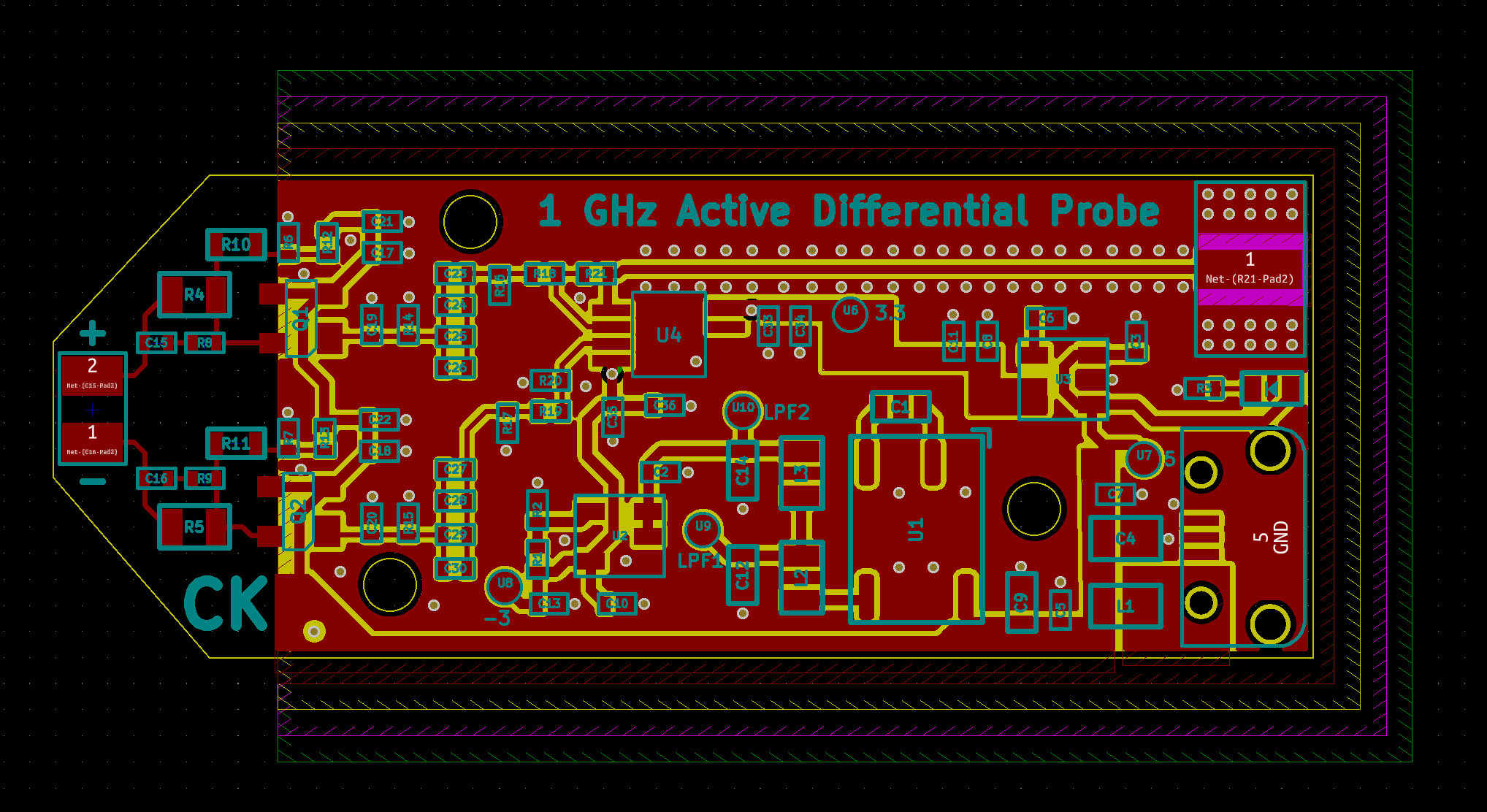
1GHZ DIFFERENTIAL PROBE is an open-source printed circuit board by ckflight, from the ckflight/1GHZ_DIFFERENTIAL_PROBE repository on GitHub. It is a 4-layer board of 48.3 × 18.5 mm with 75 parts on 32 nets, routed with 233 tracks and 114 vias.
It is built around the THS3202D and TPS72301DBV. Its parts include 36 capacitors, 21 resistors, 10 ICs, 3 inductors and 2 transistors. It belongs with the sensors and measurement boards of this library.
Instead of paying a few thousand $ to the unnecessarily expensive probes from tektronix or rigol for daily use, i made a Differential Probe which cost 15$ for 4 layer pcb and 45$ for components and it works just fine.
Mosfet source follower is used as voltage buffer which has 20dB attenuation (1/10) and an opamp subtractor is used at the end. Copper pour at the input of the pcb is removed to reduce input capacitance of the probe for high speed signals. 2 passive LPF is used at the output of Switching Regulator which is generating ripple noise. Also input power from the USB Connector is filtered with 180 Ohm Ferrite Bead which is the input of the Switching Regulator. This way of filtering is the best way of reducing ripple noise and switching peaks of the regulator. However using second LDO Regulator to filter out instead of using switching regulator is the best option for power filtering which means better high speed signal performance.
Design needs usb input power for powering the circuit and 50 Ohm SMA connector is used. BNC 50 Ohm feedthrough connector can be used for connection to Oscilloscope if it does not have 50 Ohm option.
| Qty | Value | Footprint | References |
|---|---|---|---|
| 8 | 100nF | Footprints:SMD_0402 | C5, C7, C10, C25, C29, C31, C33, C35 |
| 7 | 10nF | Footprints:SMD_0402 | C6, C8, C21, C22, C32, C34, C36 |
| 6 | 2.2uF | Footprints:SMD_0402 | C2, C3, C11, C13, C23, C27 |
| 5 | test_port | Footprints:SolderPad_1_1.2mm_SMD_Circle | U6, U7, U8, U9, U10 |
| 4 | 1nF | Footprints:SMD_0402 | C17, C18, C24, C28 |
| 4 | 442 | Footprints:SMD_0402 | R18, R19, R20, R21 |
| 4 | 50 | Footprints:SMD_0402 | R14, R15, R16, R17 |
| 2 | 0.5pF | Footprints:SMD_0402 | C15, C16 |
| 2 | 100pF | Footprints:SMD_0402 | C26, C30 |
| 2 | 10M | Footprints:SMD_0603 | R10, R11 |
| 2 | 10uF | Footprints:SMD_0603 | C12, C14 |
| 2 | 10uH | Footprints:SMD_0805 | L2, L3 |
| 2 | 200 | Footprints:SMD_0402 | R8, R9 |
| 2 | 2pF | Footprints:SMD_0402 | C19, C20 |
| 2 | 30M | Footprints:SMD_0805 | R4, R5 |
| 2 | 4.7K | Footprints:SMD_0402 | R6, R7 |
| 2 | 4.7uF | Footprints:SMD_0603 | C1, C9 |
| 2 | 6.8K | Footprints:SMD_0402 | R12, R13 |
| 2 | BF998 | Footprints:SOT143 | Q1, Q2 |
| 1 | 36.5K | Footprints:SMD_0402 | R2 |
| 1 | 470 | Footprints:SMD_0402 | R3 |
| 1 | 47uF | Footprints:SMD_0805 | C4 |
| 1 | 64.9K | Footprints:SMD_0402 | R1 |
| 1 | Connector_01x02 | Footprints:PinHeader_1x2_P2.5mm | J2 |
| 1 | Ferrite_Bead | Footprints:SMD_0805 | L1 |
| 1 | LDS3985 | Footprints:SOT23_5 | U3 |
| 1 | Led_Diode | Footprints:Diode_0603 | D1 |
| 1 | MAX1680 | Footprints:SO8_3.9X4.9mm_P1.27mm | U1 |
| 1 | SMA_Connector | Footprints:SMA_Connector | U5 |
| 1 | THS3202 | Footprints:VSSOP_8_3x3mm_P0.65mm | U4 |
| 1 | TPS72301 | Footprints:SOT23_5 | U2 |
| 1 | USB_MicroB | Footprints:USB_MicroB_TH | J1 |

CameraNexus/sitina1
Open-source 35mm full-frame (36mm x 24mm) CCD mirror-less interchangable lens camera (MILC). The original goal of this project was to create a digital camera back to convert SLR cameras to DSLR cameras, but has since…


open-ephys/oe-acquisition-board-gen3
3rd Generation Open Ephys USB Acquisition Board

OscarBazylewich/Phaser_and_Overdrive_Custom_Guitar_Pedal
This project is a guitar pedal with analog circuits. It has a four-stage JFET phaser of the MXR Phase 90 type and a diode-clipping overdrive of the BOSS OD-1 type.

loxodes/vna
Under development open hardware microwave vector network analyzer


haunma/fieldmill
Hardware and software for an electrostatic field mill
It measures 48.3 × 18.5 mm and has 4 copper layers, 1.6 mm thick.
75 parts, built around the THS3202D and TPS72301DBV. The full list of its parts is on this page, with links to each part's symbol and footprint where PCBKit's library has them.
From the ckflight/1GHZ_DIFFERENTIAL_PROBE repository on GitHub, at the commit this page was made from: the board is 1 GHz Differential Probe.kicad_pcb. PCBKit opens the board in the browser, with nothing to install.
Its repository states no licence, so its author keeps all rights: ask ckflight before reusing the design.