2 layers77 × 39 mm
 cjheath/STM32C071_Basic2
A basic template for prototype boards using the STM32F071 as a USB controller
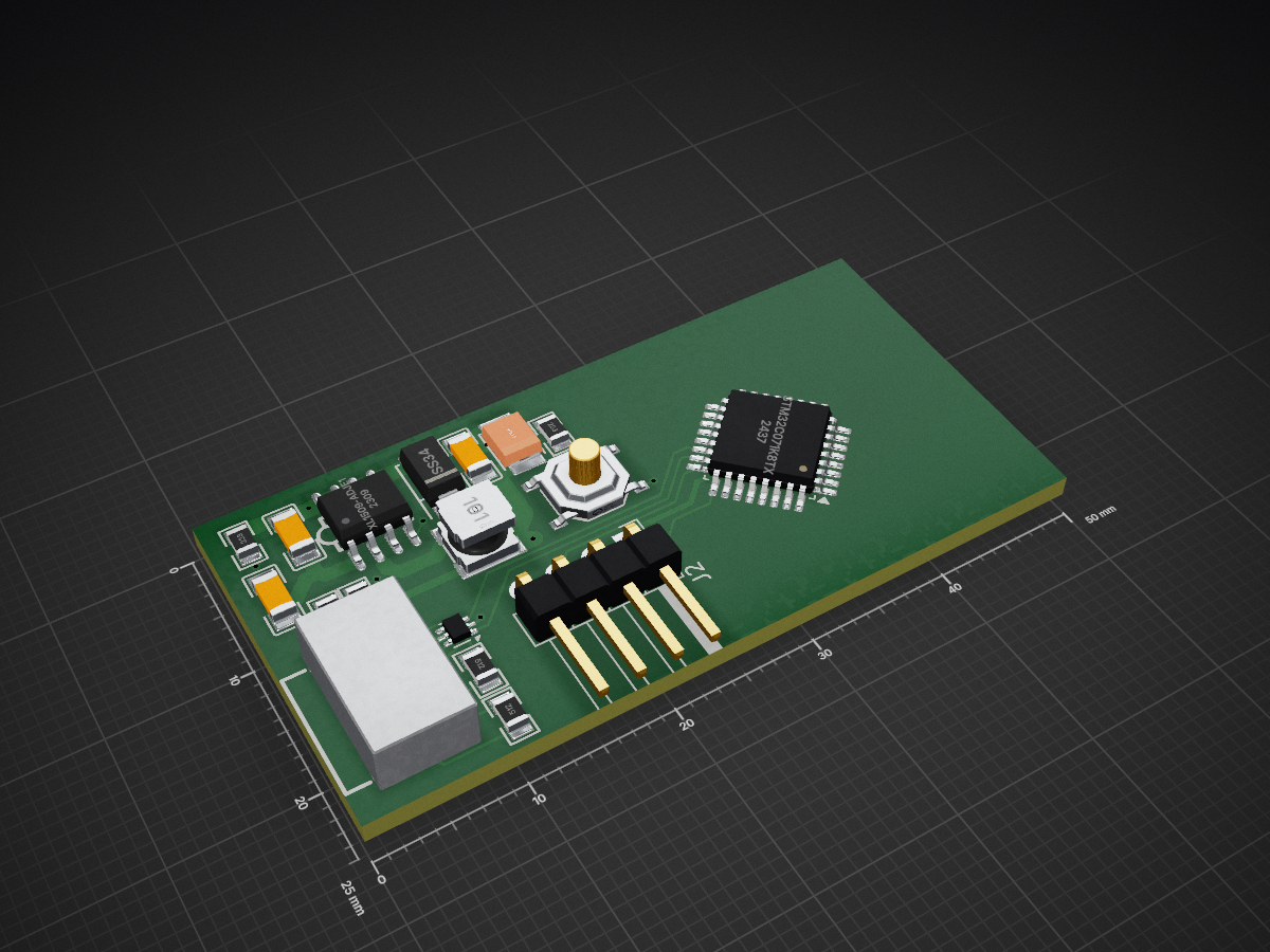
STM32C071 is an open-source printed circuit board by cjheath, from the cjheath/STM32C071_Basic repository on GitHub. It is a 2-layer board of 50 × 25 mm with 18 parts on 42 nets, routed with 183 tracks and 23 vias.
It is built around the XL1509-ADJE1, USBLC6-2P6 and SS34, with the TS-1187A-B-A-B among its other parts. Its parts include 6 resistors, 4 capacitors, 3 ICs, 2 connectors and 1 diode. It belongs with the STM32 boards of this library.


Pin functions on the MCU are configured for minimum layout complexity for UART, I2C and SPI, but KiCad knows what alternate functions are possible. If you need different pin functions, you should reconfigure them.
You may obviously change the size of the PCB by redrawing the Edge Cuts rectangle.
This Kicad project has a local project library and uses jlcbasic and jlcpreferred libraries from Github. These libraries are expected to be checked-out somewhere together, and this directory should contain a symbolic link to their parent directory. If you can't use a symbolic link, make the (libraries)[libraries] directory and check out those projects inside that.
So far as possible, parts are chosen to be easy for a relative novice to hand-solder. Accordingly, the smallest parts are 0805 packages, and the MCU is a QFP, not a leadless version. The cheapest possible parts have been chosen throughout, with a preference for JLCPCB parts that have no extra assembly changes.
The 3.2V power supply should be capable of more than 700mA, which is all the power that 5V USB guarantees. If you intend to use this much power, you should increase the size of the tantalum capacitor on the output.
The power supply is designed to sink heat to the grond plane on the back of the board. You might wish to remove the ground plane elsewhere, but consider leaving it in this area if you need low noise or heatsinking.
| Qty | Value | Footprint | References |
|---|---|---|---|
| 3 | 10uF | jlcbasic:C1206 | C3, C4, C5 |
| 2 | 22kΩ | jlcbasic:R0805 | R5, R6 |
| 2 | 5.1kΩ | jlcbasic:R0805 | R1, R2 |
| 1 | 100uF | jlcbasic:CASE-B_3528 | C2 |
| 1 | 100uH | project:IND-SMD_L4.0-W4.0_SMNR4030 | L1 |
| 1 | 2.7kΩ | jlcbasic:R0805 | R3 |
| 1 | 4.7kΩ | jlcbasic:R0805 | R4 |
| 1 | Conn_01x04_Pin | Connector_PinHeader_2.54mm:PinHeader_1x04_P2.54mm_Horizontal | J2 |
| 1 | SS34 | jlcbasic:SMA_L4.3-W2.6-LS5.2-RD | D1 |
| 1 | STM32C071K8Tx | Package_QFP:LQFP-32_7x7mm_P0.8mm | U1 |
| 1 | TS-1187A-B-A-B | jlcbasic:SW-SMD_4P-L5.1-W5.1-P3.70-LS6.5-TL_H1.5 | SW1 |
| 1 | USBLC6-2P6 | Package_TO_SOT_SMD:SOT-666 | U2 |
| 1 | USB_C_Receptacle_USB2.0_16P | project:USB-C-SMD_TYPE-C-USB-17 | J1 |
| 1 | XL1509-ADJE1 | jlcpreferred:SOIC-8_L5.0-W4.0-P1.27-LS6.0-BL | U4 |
It measures 50 × 25 mm and has 2 copper layers, 1.6 mm thick.
18 parts, built around the XL1509-ADJE1, USBLC6-2P6, SS34 and TS-1187A-B-A-B. The full list of its parts is on this page, with links to each part's symbol and footprint where PCBKit's library has them.
From the cjheath/STM32C071_Basic repository on GitHub, at the commit this page was made from: the board is Hardware/STM32C071.kicad_pcb and its schematic Hardware/STM32C071.kicad_sch. PCBKit opens the board in the browser, with nothing to install.
Its repository states no licence, so its author keeps all rights: ask cjheath before reusing the design.


LECTIX/LEC000042-Detecteur-de-presence-DCC-Analogique-1A
Fichiers sources pour le produit LEC000042


skogaby/skogaslider
Firmware, CAD, and PCB files for the skogaslider, an RP2040-based controller to simulate Chunithm's gameplay experience

aeremin/firefly_zephyr
Firmware (Zephyr RTOS / nRF Connect SDK, with Pigweed libraries), custom boards and KiCad hardware projects for a few small nRF52-based devices.