2 layers123.8 × 45.2 mm
Led board
chrisgian05/Digital_LED_clock
A 6-digit 7-segment clock (HH:MM:SS) built around an ATmega328P, an external RTC, and a constant-current LED driver — split across two custom PCBs I designed in KiCad.
11 parts
 chrisgian05/Digital_LED_clock
A 6-digit 7-segment clock (HH:MM:SS) built around an ATmega328P, an external RTC, and a constant-current LED driver — split across two custom PCBs I designed in KiCad.
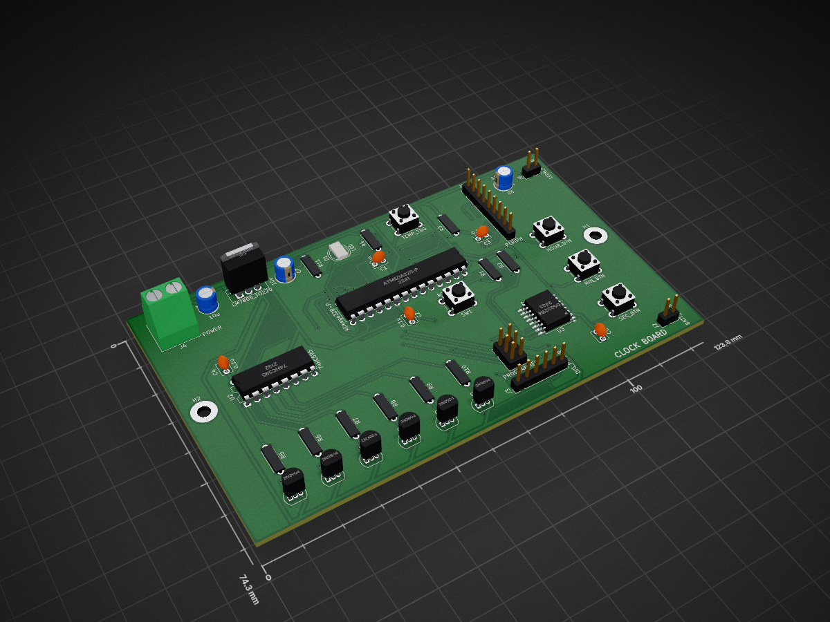
Clock board is an open-source printed circuit board by chrisgian05, from the chrisgian05/Digital_LED_clock repository on GitHub. It is a 2-layer board of 123.8 × 74.3 mm with 43 parts on 52 nets, routed with 467 tracks and 73 vias.
It is built around the ATMEGA328-PU, 74HC595 and DS3231MZ+. Its parts include 11 resistors, 8 capacitors, 6 transistors, 6 connectors and 5 switches. It belongs with the lEDs and displays boards and the AVR (ATmega, ATtiny) boards of this library.


A 6-digit 7-segment clock (HH:MM:SS) built around an ATmega328P, an external RTC, and a constant-current LED driver — split across two custom PCBs I designed in KiCad. This was mostly an excuse to actually use everything I've learned so far about digital electronics and embedded C in one project I could see and touch, instead of another breadboard that gets torn down at the end of the semester.
Two boards, connected by a short ribbon cable:
clock_board — the "brains." ATmega328P, DS3231 RTC, a 74HC595
shift register + 6 transistors for digit selection, an ISP header
for programming, and the 4 push buttons.led_board — the "face." A TLC5916 constant-current LED driver
feeding three 2-digit common-anode 7-segment modules (6 digits
total), plus the transistor-switched power lines coming in from the
clock board.Full schematics and PCB layouts are in hardware/, one
subfolder per board. Both were designed from scratch in KiCad — no
dev-board shields, no premade modules other than the RTC/driver ICs
themselves.
Bare-metal AVR C — no Arduino core, straight avr-libc and direct
register access. I wanted to actually deal with I2C, timers, and
interrupts myself instead of hiding behind Wire.h and digitalWrite.
twi.c — hardware I2C driver for talking to the DS3231ds3231.c — RTC register access (BCD conversion, get/set time, temperature)display.c — 7-segment font table + the Timer1 interrupt that handles
digit multiplexing (bit-banging both the 74HC595 and TLC5916 shift chains)buttons.c — debounced button reads with auto-repeat on holdmain.c — main loop tying it all togetherAll of it lives in firmware/, buildable with either the
included Makefile or platformio.ini.
Schematics and PCBs are designed; firmware is written and reviewed but
not yet validated on the assembled board (still waiting on
boards/soldering as of writing this). A couple of polarity assumptions
(digit-select active-high/low, segment driver active-high/low) are
flagged with #defines in firmware/src/config.h specifically because
they're easier to confirm with a multimeter on the real board than to
guess from a schematic.
| Qty | Value | Footprint | References |
|---|---|---|---|
| 8 | 10K | Resistor_THT:R_Axial_DIN0207_L6.3mm_D2.5mm_P7.62mm_Horizontal | R3, R4, R5, R6, R7, R8, R9, R10 |
| 6 | 2N3904 | Package_TO_SOT_THT:TO-92_Inline | Q1, Q2, Q3, Q4, Q5, Q6 |
| 5 | 0.1u | Capacitor_THT:C_Disc_D3.8mm_W2.6mm_P2.50mm | C1, C2, C3, C4, C5 |
| 3 | 1Ou | Capacitor_THT:CP_Radial_D5.0mm_P2.00mm | C6, C7, C8 |
| 2 | 4.7k | Resistor_THT:R_Axial_DIN0207_L6.3mm_D2.5mm_P7.62mm_Horizontal | R1, R2 |
| 2 | MountingHole | MountingHole:MountingHole_3.2mm_M3_Pad | H1, H2 |
| 1 | 200 | Resistor_THT:R_Axial_DIN0207_L6.3mm_D2.5mm_P7.62mm_Horizontal | R11 |
| 1 | 74HC595 | Package_DIP:CERDIP-16_W7.62mm_SideBrazed | U2 |
| 1 | ATmega328-P | Package_DIP:DIP-28_W7.62mm | U1 |
| 1 | BATT_Conn | Connector_PinHeader_2.54mm:PinHeader_1x02_P2.54mm_Vertical | J2 |
| 1 | DIG_POWER | Connector_PinHeader_2.54mm:PinHeader_1x06_P2.54mm_Vertical | J3 |
| 1 | DS3231M | Package_SO:SOIC-16W_7.5x10.3mm_P1.27mm | U3 |
| 1 | HOUR_BTN | Button_Switch_THT:SW_PUSH_6mm_H5mm | SW2 |
| 1 | LED | LED_THT:LED_D5.0mm | D1 |
| 1 | LEDB_POWER | Connector_PinHeader_2.54mm:PinHeader_1x02_P2.54mm_Vertical | J6 |
| 1 | LM7805_TO220 | Package_TO_SOT_THT:TO-220-3_Vertical | U4 |
| 1 | MIN_BTN | Button_Switch_THT:SW_PUSH_6mm_H5mm | SW3 |
| 1 | PERIPH | Connector_PinHeader_2.54mm:PinHeader_1x09_P2.54mm_Vertical | J1 |
| 1 | POWER | TerminalBlock_Phoenix:TerminalBlock_Phoenix_MKDS-1,5-2_1x02_P5.00mm_Horizontal | J4 |
| 1 | PROGRAMMER | Connector_PinHeader_2.54mm:PinHeader_2x03_P2.54mm_Vertical | J5 |
| 1 | RST_uC | Button_Switch_THT:SW_PUSH_6mm_H5mm | SW1 |
| 1 | SEC_BTN | Button_Switch_THT:SW_PUSH_6mm_H5mm | SW4 |
| 1 | TEMP_TOG | Button_Switch_THT:SW_PUSH_6mm_H5mm | SW5 |
chrisgian05/Digital_LED_clock
A 6-digit 7-segment clock (HH:MM:SS) built around an ATmega328P, an external RTC, and a constant-current LED driver — split across two custom PCBs I designed in KiCad.

crnkovicaaron/launchclock
Key components: - MCU: ATmega328P - RTC: DS3231M with CR1220 battery backup - Displays: MAX7219-driven dual 4-digit 7-segment (5641AS) and 8x8 dot matrix (1088AS) - Input: 4x4 matrix keypad - Power: 5V DC via 5.5x2.1mm…


ThomasVDD/SmartSupply
SmartSupply is a digital battery powered lab powersupply. It is Arduino compatible and can be controlled via PC over USB.

slu4coder/Minimal-UART-Computer-3
Version 3 of my educational DIY TTL computer built around a UART serial interface - now with blinkenlights!

hkzlab/ROsiM
ROsiM is a ROM simulator/emulator, supporting up to 512k/16bit ROMs
It measures 123.8 × 74.3 mm and has 2 copper layers, 1.6 mm thick.
43 parts, built around the ATMEGA328-PU, 74HC595 and DS3231MZ+. The full list of its parts is on this page, with links to each part's symbol and footprint where PCBKit's library has them.
From the chrisgian05/Digital_LED_clock repository on GitHub, at the commit this page was made from: the board is hardware/clock_board/clock_board.kicad_pcb and its schematic hardware/clock_board/clock_board.kicad_sch. PCBKit opens the board in the browser, with nothing to install.
Its repository states no licence, so its author keeps all rights: ask chrisgian05 before reusing the design.