2 layers191.3 × 169.2 mm

 choicebuilds/SumoBot-v2
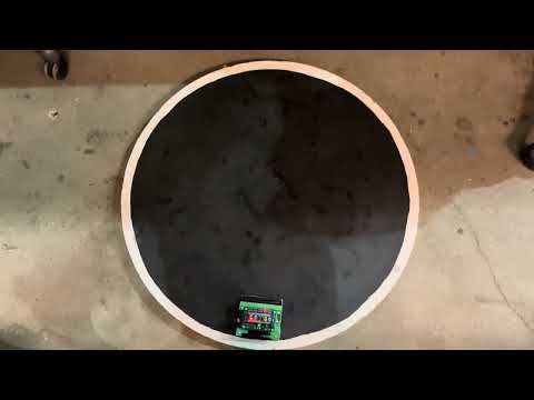
A Robojackets robot (v2) built from scratch, featuring a custom 4-layer PCB, STM32-based (ARM Cortex-M3) firmware written in C (STM32CubeMX + CMake), and a 3D-printed chassis.
Kamikazii is an open-source printed circuit board by choicebuilds, from the choicebuilds/SumoBot-v2 repository on GitHub. It is a 4-layer board of 75 × 49 mm with 59 parts on 57 nets, routed with 563 tracks and 153 vias.
It is built around the DRV8871DDARQ1, L7805CV and 210-4MS. Its parts include 20 capacitors, 12 diodes, 9 resistors, 4 ICs and 3 switches. It belongs with the STM32 boards of this library.


A significantly improved version of SumoBot v1! Concise documentation intended as a project showcase for my portfolio/resume.

Notable Improvements:


With the JLCPCB Stencil: $14.16 (PCB) + $21.69 (Shipping) - $5 (Coupon) = $30.85 + Tax
Without the JLCPCB Stencil: $7 (PCB) + $3.12 (Shipping) - $5 (Coupon) = $5.12 + Tax
I went with the second option and generated a stencil using the LPKF Protolaser.


I would not recommend, especially for a small PCB, because the stencil did not sit flat. Required a few manual adjustments.

Then, a reflow oven was used for SMD components:


And the remaining components were through-hole soldered.
I flipped the polarity of the XT-30 connector on the silkscreen without reverse-polarity protection:

It made a very loud sound when the bulk capacitor blew up. Lesson learned to always double check.
| Qty | Value | Footprint | References |
|---|---|---|---|
| 15 | 100n | Capacitor_SMD:C_0402_1005Metric | C02, C03, C05, C07, C08, C09, C10, C11, C12, C13, C15, C16, C18, C19, C20 |
| 7 | 1k | Resistor_SMD:R_0402_1005Metric | R01, R02, R03, R04, R05, R06, R07 |
| 7 | LED | LED_SMD:LED_0402_1005Metric | D11, D12, D13, D14, D15, D16, D17 |
| 5 | Distance Sensor | TerminalBlock:TerminalBlock_Xinya_XY308-2.54-3P_1x03_P2.54mm_Horizontal | D1, D2, D3, D4, D5 |
| 4 | M3 | MountingHole:MountingHole_3.2mm_M3 | H1, H2, H3, H4 |
| 3 | 47u | Capacitor_SMD:C_1210_3225Metric | C04, C06, C14 |
| 2 | 30K | Resistor_SMD:R_0402_1005Metric | R08, R09 |
| 2 | DRV8871DDAR | DRV8871DDAR:VREG_LM5017MR_NOPB | U1, U2 |
| 2 | Line Sensor | TerminalBlock:TerminalBlock_Xinya_XY308-2.54-3P_1x03_P2.54mm_Horizontal | L1, L2 |
| 2 | Motor | TerminalBlock:TerminalBlock_Xinya_XY308-2.54-2P_1x02_P2.54mm_Horizontal | M1, M2 |
| 2 | Servo | Connector_PinHeader_2.54mm:PinHeader_1x03_P2.54mm_Vertical | S1, S2 |
| 1 | 210-4MS | 210-4MS:210-4MS | SW1 |
| 1 | 330n | Capacitor_SMD:C_0402_1005Metric | C01 |
| 1 | 470u | Capacitor_THT:CP_Radial_D8.0mm_P3.50mm | C17 |
| 1 | BP | blue_pill:blue_pill | U3 |
| 1 | L7805CV | L7805CV:TO255P1040X460X1968-3 | U4 |
| 1 | On/Off | Connector_PinHeader_2.54mm:PinHeader_1x03_P2.54mm_Vertical | T1 |
| 1 | Remote Start | Connector_PinHeader_2.54mm:PinHeader_1x03_P2.54mm_Vertical | T2 |
| 1 | XT30 | Connector_AMASS:AMASS_XT30U-F_1x02_P5.0mm_Vertical | JB1 |


justinlindh/digits
Encrypted retro phone network — private VoIP over vintage desk phones

shmuelzon/lowkey
Matter-over-Thread and/or BLE in-door smart lock controller based on the RBM1 lock body


gonewx/quadcuber
本目录是 A1 电子源目录。打开 quadcuber.kicadpro,包含原生可编辑原理图和四层 PCB、本地符号/封装库。本设计为单块PCB,RP2040、QSPI Flash、晶振、USB-C、驱动和电源均直接焊接在板上;A0的Pico H插装已移除。马达使用EV3裸插座。接线定义仍从 ../wiring/spec.py 导入,固件未改动,也没有把 R/L 固件描述成已支持四臂控制。

ivanchairez01/indMotorControl
STM32-based industrial motor controller featuring FreeRTOS, CAN networking, closed-loop PID speed control, fault management, and real-time diagnostics.

Matthew-Bon/moon_child
A rocket flight computer to support CBJAMO's amoral interests.
It measures 75 × 49 mm and has 4 copper layers, 1.6 mm thick.
59 parts, built around the DRV8871DDARQ1, L7805CV and 210-4MS. The full list of its parts is on this page, with links to each part's symbol and footprint where PCBKit's library has them.
From the choicebuilds/SumoBot-v2 repository on GitHub, at the commit this page was made from: the board is hardware/Kamikazii.kicad_pcb and its schematic hardware/Kamikazii.kicad_sch. PCBKit opens the board in the browser, with nothing to install.
Its repository states no licence, so its author keeps all rights: ask choicebuilds before reusing the design.