2 layers14 × 49.5 mm

 cheyao/ch32-logic-analyzer4
200MHz USB 3.1 logic analyzer and 20MHz ADC w/ pulseview
Logic analyzer is an open-source printed circuit board by cheyao, from the cheyao/ch32-logic-analyzer repository on GitHub. It is a 4-layer board of 45.2 × 40.4 mm with 100 parts on 126 nets, routed with 1,519 tracks and 194 vias.
It is built around the CH32H417MEU6, LMV321IDCKT and TPD4EUSB30DQAR, with the AMS1117-3.3, TMUXHS4212RKSR and CC0402KRX7R7BB104 among its other parts. Its parts include 43 capacitors, 31 resistors, 7 ICs, 5 connectors and 3 diodes. It belongs with the sensors and measurement boards of this library.


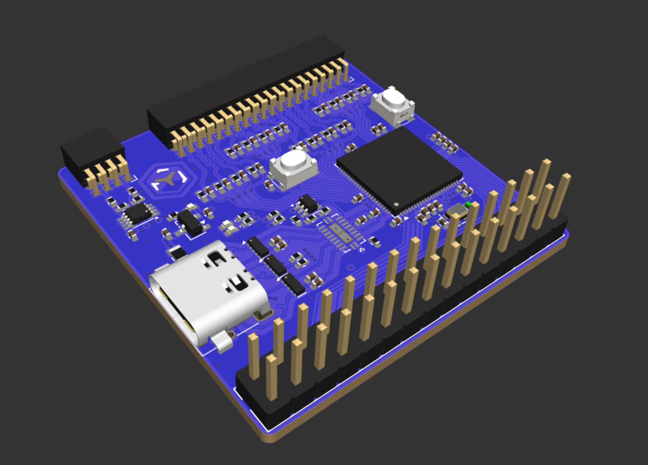
This is a cheap 200Msps logic analyzer with a 20Msps analog component. It uses USB 3.2 to send data to the computer, and can also act as a ch32h417 development board.
It is usable with pulseview delivering a beautiful interface and allowing you to view all kinds of diffrent protocols. And with voltage changing, it supports 1.2V, 3.3V and 5V opration modes.
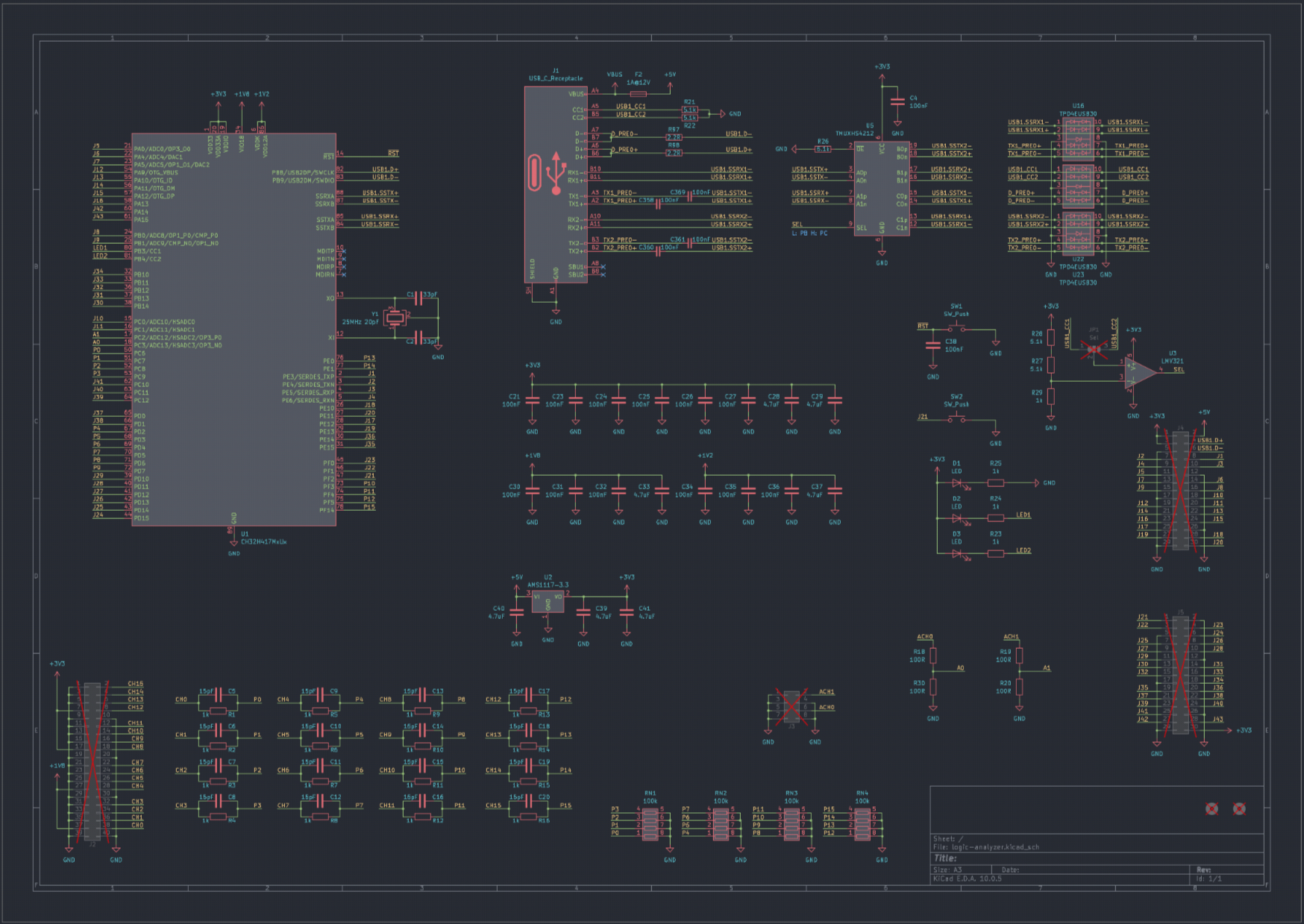
The analog channels support 20Msps at 10bit accuracy, or 5MHz at 12bit accuracy. Input range is from 0V to 5V, and it supports external triggering too!
The bottom row of header breaks out GPIO pins of various protocols, allowing the board to also become a devboard that can be programed via USB.
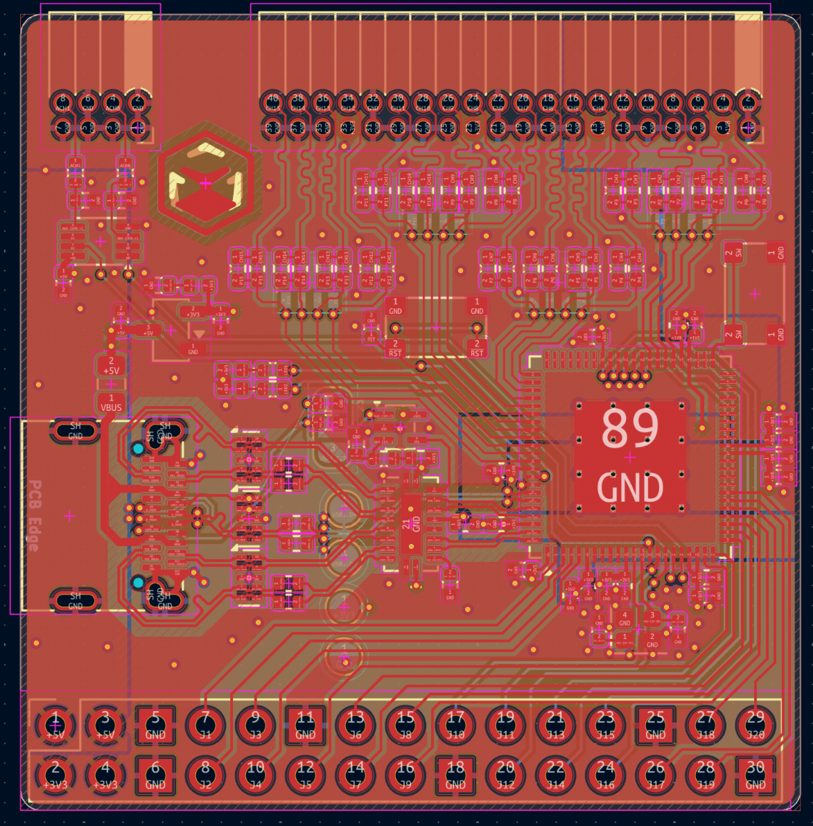
The PCB is a 4-layered board in order to preserve signal intergity on the USB 3.2 data lines. With high-quality TI active components to preserve signal quality.
| Qty | Value | Footprint | References |
|---|---|---|---|
| 18 | 100nF | Capacitor_SMD:C_0402_1005Metric | C21, C23, C24, C25, C26, C27, C30, C31, C32, C34, C35, C36, C358, C359, C360, C361 +2 |
| 16 | 15pF | Capacitor_SMD:C_0402_1005Metric_Pad0.74x0.62mm_HandSolder | C5, C6, C7, C8, C9, C10, C11, C12, C13, C14, C15, C16, C17, C18, C19, C20 |
| 16 | 1k | Resistor_SMD:R_0402_1005Metric_Pad0.72x0.64mm_HandSolder | R1, R2, R3, R4, R5, R6, R7, R8, R9, R10, R11, R12, R13, R14, R15, R16 |
| 7 | 4.7uF | Capacitor_SMD:C_0402_1005Metric | C28, C29, C33, C37, C39, C40, C41 |
| 5 | 5.1k | Resistor_SMD:R_0402_1005Metric | R21, R22, R26, R27, R28 |
| 4 | 100R | Resistor_SMD:R_0402_1005Metric | R18, R19, R20, R30 |
| 4 | 100k | Resistor_SMD:R_Array_Convex_4x0603 | RN1, RN2, RN3, RN4 |
| 4 | 1k | Resistor_SMD:R_0402_1005Metric | R23, R24, R25, R29 |
| 3 | LED | LED_SMD:LED_0402_1005Metric | D1, D2, D3 |
| 3 | TPD4EUSB30 | Package_SON:USON-10_2.5x1.0mm_P0.5mm | U16, U22, U23 |
| 2 | 2.2R | Resistor_SMD:R_0402_1005Metric | R97, R98 |
| 2 | 33pF | Capacitor_SMD:C_0402_1005Metric | C1, C2 |
| 2 | Conn_02x15 | Connector_PinHeader_2.54mm:PinHeader_2x15_P2.54mm_Vertical | J4, J5 |
| 2 | MountingHole | logic-analyzer:Icy Electronics Logo | H1, H2 |
| 2 | SW_Push | logic-analyzer:SW_Push_SPST_TSA016 | SW1, SW2 |
| 1 | 1A@12V | Fuse:Fuse_0805_2012Metric | F2 |
| 1 | 25MHz 20pF | Crystal:Crystal_SMD_2016-4Pin_2.0x1.6mm | Y1 |
| 1 | AMS1117-3.3 | Package_TO_SOT_SMD:SOT-89-3 | U2 |
| 1 | CH32H417MxUx | logic-analyzer:QFN-88-1EP_10x10mm_P0.4mm_EP5.7x5.7mm_ThermalVias | U1 |
| 1 | Conn_02x04 | Connector_PinHeader_1.27mm:PinHeader_2x04_P1.27mm_Horizontal | J3 |
| 1 | Conn_02x20 | Connector_PinHeader_1.27mm:PinHeader_2x20_P1.27mm_Horizontal | J2 |
| 1 | LMV321 | Package_TO_SOT_SMD:SOT-353_SC-70-5 | U3 |
| 1 | Sel | Jumper:SolderJumper-3_P1.3mm_Bridged12_RoundedPad1.0x1.5mm | JP1 |
| 1 | TMUXHS4212 | Package_DFN_QFN:DHVQFN-20-1EP_2.5x4.5mm_P0.5mm_EP1x3mm | U5 |
| 1 | USB_C_Receptacle | logic-analyzer:USB_C_Receptacle_SHOU-HAN_24P-QT | J1 |
It measures 45.2 × 40.4 mm and has 4 copper layers, 1.58 mm thick.
100 parts, built around the CH32H417MEU6, LMV321IDCKT, TPD4EUSB30DQAR and AMS1117-3.3. The full list of its parts is on this page, with links to each part's symbol and footprint where PCBKit's library has them.
From the cheyao/ch32-logic-analyzer repository on GitHub, at the commit this page was made from: the board is hardware/logic-analyzer.kicad_pcb and its schematic adaptor/adaptor.kicad_sch. PCBKit opens the board in the browser, with nothing to install.
Its repository states no licence, so its author keeps all rights: ask cheyao before reusing the design.

stanleyondrus/ILDAWaveX16
ILDAWaveX16 is an open-source, high-resolution, wireless laser DAC with SD-card playback, network control, and ILDA output.

the78mole/jumpstarter-mono
This is a monorepo containing all jumpstarter tools and (hopefully) adds a standalone server soon.


alex1klimovich/nrf52840-macro-controller
Custom nRF52840 productivity controller for digital artists — PCB, BLE/USB firmware, OLED, haptics, RGB, and enclosure CAD.

