

2 layers90 × 72 mm
 chazlambo/CubeSolverProject
All code for my Rubix Cube Solving Machine
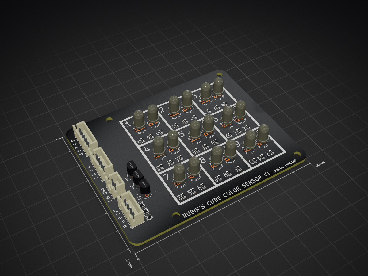
ColorSensor is an open-source printed circuit board by chazlambo, from the chazlambo/CubeSolverProject repository on GitHub. It is a 2-layer board of 90 × 72 mm with 64 parts on 48 nets, routed with 321 tracks and 34 vias.
It is built around the PT334-6C and PN2222A. Its parts include 39 resistors, 12 transistors, 9 diodes and 4 connectors. It belongs with the robots and motor control boards of this library.
A self-contained Rubik's Cube solving robot: six stepper-driven faces, two servo grippers on a moving ring, eighteen color sensors, an on-board Kociemba two-phase solver, and a 320×240 display. Scan, solve, execute — no PC involved.
Everything here is one person's design: mechanical (SolidWorks), electrical (KiCad), and firmware (Teensy 4.1).
Working: full autonomous scan → solve → execute cycle, driven from the panel menu: the five Modes (Scramble Solve, Idle, Demo, Step Solve, Patterns), on-panel tuning with defaults in source and overrides in EEPROM, a hardware jog page, live sensor diagnostics, an EEPROM fault log and lifetime stats. The display stays live during scan and solve, the abort chord works throughout, encoder faults are detected and handled, a scan is validated piece-by-piece with automatic repair, and color classification carries a per-sensor confidence.
Known unfinished:
VirtualCube::rebuildFromCubeArray() — still labeled UNFINISHED NEEDS DEBUGGING in its header, but the body is live and the firmware now relies
on it (Cube State and pattern completion refresh the color array through
it). The stale part is the label, not the code; it has no rollback on
failure, which no current caller needs.0 for all six sticker colors in every archived calibration run. The firmware
now detects this (ColorSensor::checkSensorHealth) but it is a hardware fault.MultiStepper is constant
speed by design). Left as-is deliberately — a ramp would slow the solve.Code/Main Code/CubeSolver/CubeSolver.ino — that's the program.
Everything under Code/Test Code/ is bring-up and calibration tooling. The ones
still worth keeping:
| Sketch | Purpose |
|---|---|
Test Code/Bench_Tune | Headless Serial protocol for scripted tuning: moves, parameters, every encoder before/after each move. Driven by Code/tools/bench.py |
Test Code/Actuator_Test | Serial menu for manual moves and jam-recovery testing |
Test Code/Test_Motor_Calibrate | Motor encoder calibration (also Settings → Calibration → Motor Positions) |
Test Code/Test_Color_Calibrate | Color calibration (also Settings → Calibration → Color Sensors) |
Test Code/I2C_Search | Bus scanner — genuinely useful on a five-mux rig |
Test Code/Test_Menu | Menu, wheel and panel bench test — see below |
Test Code/Test_Menu drives the same CubeMenu and CubeDisplay the
firmware does, so anything that feels wrong there feels wrong in the firmware.
It runs no scan, solve or calibration. It does move real hardware from three
places: Load / Eject, the Actuators page (every servo and ring
position, each face motor and both whole-cube rotations, one part at a time),
and Diagnostics → Tuning → Servos, which drives a horn to each value as you
dial it. Everything under Screens is drawing only.
It also carries a Screens submenu that draws each operation screen (scan step
rows, calibration color chips, the solve progress bar, the error look) from
canned data, so the panel can be judged and photographed in seconds instead of
by running a 40-second scan to check one label. Input Report is a live
readout of the wheel count and every button — the fastest way to spot a flaky
encoder or a dead button.
It runs in the simulator too, with no machine at all:
cmake -S Code/sim -B Code/sim/build-test -DSIM_SKETCH=Test_Menu
cmake --build Code/sim/build-test -j && ./Code/sim/build-test/cubesim
Test Code/_Archive/ does not compile against the current tree (it includes a
Cube.h that no longer exists). Git history is the archive.
Board: Teensy 4.1. Not a 4.0 — the solver's lookup tables alone are 4.14 MiB, which is 214% of a 4.0's flash, and pins 40/41 don't exist on a 4.0.
Toolchain: Arduino IDE + Teensyduino.
TODO: record the exact Arduino IDE and Teensyduino versions you build with, plus CPU speed and USB type from the Tools menu.
Sketchbook layout — this is the non-obvious step. Code/libraries/ is an
Arduino sketchbook libraries folder, and the build must compile the repo's
copy, not a stale one. Two working setups:
Code/ directory (File → Preferences → Sketchbook location). Then
#include <CubeSystem.h> and #include <kociemba.h> resolve, and
lv_conf.h is found automatically.Documents/Arduino so Library Manager installs
land in the usual place):
Documents/Arduino/libraries/CubeSolver → symlink to
Code/libraries/CubeSolverDocuments/Arduino/libraries/kociemba → junction to
Code/libraries/kociembaDocuments/Arduino/libraries/lv_conf.h → a one-line forwarder header
that does #include "../../Projects/Cube_Solver/Code/libraries/lv_conf.h"Either way, do not copy the libraries into the sketchbook — you'll edit
the repo and build a stale copy. And never place an lv_conf.h inside the
lvgl library folder itself: if lvgl's own directory ever lands on the
include path, __has_include("lv_conf.h") silently builds the whole project
against that copy instead of the repo's.
None of these are vendored except Kociemba. Install via Library Manager unless noted.
| Library | Source | Notes |
|---|---|---|
| AccelStepper | Library Manager / airspayce.com | GPL-2.0 |
| MultiStepper | ships inside AccelStepper | constant-speed by design |
| PWMServo | bundled with Teensyduino | Teensy-only; not the stock Servo |
| TCA9548 | RobTillaart/TCA9548 | I²C multiplexer |
| veml6040 | ThingPulse/VEML6040 | color sensors |
| RunningMedian | RobTillaart/RunningMedian | scan filtering |
| Adafruit_seesaw | Adafruit | ANO scroll-wheel breakout |
| ILI9341_T4 | vindar/ILI9341_T4 (GitHub) | Teensy-4-specific DMA driver |
| LVGL | lvgl/lvgl | v9.x — the code uses v9-only APIs |
| EEPROM / Wire | Teensyduino core | two I²C buses used |
| SPI | Teensyduino core | pulled in transitively by ILI9341_T4, not included directly |
| kociemba | vendored at Code/libraries/kociemba/ | from vindar/kociemba |
TODO: pin the versions you actually build against, especially LVGL — the code uses
lv_display_create/lv_tick_set_cb, which are v9-only.
The menu's look is generated, not hand-drawn. docs/theme/ holds the design as
two HTML files, and Code/tools/bake_theme.py rasterizes those same files
through headless Chrome at the panel's native 320x240, then packs the result
into LVGL C arrays under Code/libraries/CubeSolver/utility/:
python3 Code/tools/bake_theme.py              # images + fonts (needs network)
python3 Code/tools/bake_theme.py --no-fonts   # images only
The generated files are committed, so a normal build needs none of this —
run it only after changing the design. It needs google-chrome, python3-pil,
and npx for the font conversion.
Two things about those assets are load-bearing and easy to undo by accident:
utility/. Code/libraries/CubeSolver has no
library.properties, so the Arduino IDE treats it as a 1.0-format library and
compiles only the library root and utility/. Assets moved to a prettier
subdirectory are silently not compiled, and the sketch fails to link.LV_USE_LOG at 0 it fails silently, drawing nothing at all. This costs
about 220 KB of flash and is worth it.Total asset cost: ~565 KB of flash, against the ~3.3 MB left after the solver's own 4.14 MiB of lookup tables. RAM is unchanged.
Code/libraries/lv_conf.h is required and its settings are not defaults.
LV_COLOR_DEPTH 16 must match what ILI9341_T4 expects; a mismatch does not fail
to build, it renders wrong colors and looks like a hardware fault. See the
comments in that file for the load-bearing settings.
LV_MEM_SIZE is 64 KB, and running out of it hangs the machine.
LV_USE_ASSERT_MALLOC is 1 and LVGL's default assert handler is while(1);, so
an exhausted pool is not a degraded UI — it is a halt, with no message, because
LV_USE_LOG is 0. It started at 32 KB, which the themed menu alone came within
~1 KB of; the operation screens took the peak to ~27 KB and the firmware hung
at boot with no output at all, so it went to 48 KB. The Sensor Test chips then
took the widget set to 35 KB and tripped the boot warning below, so it went to
64 KB. Every raise was set against a measurement, not a guess.
Two things watch this now: CubeDisplay::begin() prints the pool usage over
Serial once every widget exists, and warns below 8 KB free; and M in the
desktop simulator prints it live. Check the boot line before assuming a new
screen is free.
Verified against the TEENSY_4.1 footprint's pad-to-net mapping in
Circuitry/KiCad/Cube Solver/Motherboard/Motherboard.kicad_pcb.
Code/libraries/CubeSolver/CubeHardwareConfig.cpp is the single source of truth
in firmware.
| Pin | Signal | Pin | Signal |
|---|---|---|---|
| 0 / 1 | U step / dir | 18 / 19 | I²C0 SDA / SCL |
| 2 / 3 | R step / dir | 22 / 23 | Bottom / Top servo |
| 4 / 5 | F step / dir | 24 / 25 | B step / dir |
| 6 / 7 | D step / dir | 26 | Stepper enable (all 7) |
| 8 / 9 | L step / dir | 28 / 29 | Ring step / dir |
| 10 | Display DC | 30 | Encoder mux /RESET |
| 11 / 12 | Display MOSI / MISO | 32 | Power sense |
| 13 | Display SCK (+ onboard LED) | 40 / 41 | Color LED 2 / 1 |
| 14 / 15 | Display CS / RESET | 16 / 17 | I²C1 SCL / SDA — see note |
I²C addresses
| Addr | Device | Bus |
|---|---|---|
0x70 | TCA9548 — encoder mux (7 AS5600 behind it) | Wire |
0x74–0x75 | TCA9548 ×2 — color board 1 | Wire |
0x76–0x77 | TCA9548 ×2 — color board 2 | Wire |
0x36 | AS5600 magnetic encoder ×7 | Wire (behind mux) |
0x10 | VEML6040 ×18 | Wire (behind muxes) |
0x49 | Adafruit seesaw (ANO wheel) | Wire1 |
No pin or address conflicts.
The firmware puts the scroll wheel on Wire1 (pins 16/17), but Motherboard Rev A routes connector J17 to Wire0 (pins 18/19), and Teensy pads 16/17 are marked unconnected. Since the machine works, there must be a bodge wire.
TODO: confirm the bodge and either roll it into a Rev B or note it on the board. Right now this exists only in the hardware and in your head.
The color scanner is mounted rotated 90° from its original layout. It
was turned in CAD to make the assembly fit, which changed which faces each
scan pass reads — from [L,B] [U,F] [D,R] to
[Back,Right] [Left,Down] [Up,Front] — and no firmware changed, because
scanCube() identifies each face from its own centre color rather than
assuming which one it is looking at. What the design does rely on is the two
sensors' position relative to each other, and rotating the whole assembly
preserves that. Moving one sensor relative to the other would not, and would
break left1/left2 in scanCube().
The only thing tracking the physical order is kScanPassFaces in
CubeOpShape.cpp, which fills the panel's face row during a scan. Rotate the
scanner again and that table is the one thing to update.
Two other things worth knowing:
Wire2, consumed by the B stepper. There is no third
I²C bus available without moving that motor.Order matters — the solver needs both calibrations, and color calibration needs motors that already home correctly.
Menu → Settings → Calibration → Motor Positions, or flash
Test Code/Test_Motor_Calibrate.
Records four encoder positions per motor, one per quarter turn, into EEPROM.
TODO: describe the physical setup — how the fingers should be positioned relative to the cube before starting, what a good result looks like, and when this needs redoing after a mechanical change.
Menu → Settings → Calibration → Color Sensors, or flash
Test Code/Test_Color_Calibrate.
Needs a solved cube. Steps through orientations recording a reference RGBW per color per sensor, plus an "empty chamber" reference.
The firmware now derives a per-sensor decision threshold from this data
(ColorSensor::computeSeparations) rather than using one global tolerance, so a
bad calibration degrades classification measurably. Check the health report.
TODO: describe ambient lighting conditions, whether the lid should be on, and how to tell a good calibration from a marginal one.
Menu → Settings → Calibration → Servo Positions. Rows preview live as the wheel turns, behind a red confirm; values persist in the tuning EEPROM block.
The compiled defaults live in the shared parameter table
(Code/libraries/CubeSolver/CubeTuneTable.cpp), not in
CubeHardwareConfig.cpp — the topExtPos / botExtPos globals there are read
once at servo construction and then overridden at boot by the table, so editing
them no longer changes the machine.
TODO: record how the defaults were determined and how to retune after changing a servo horn or linkage.
Abort: hold SELECT and LEFT together for 1.5 s during a scan or solve. The machine stops at the next mechanically safe point, releases the cube, and returns to the menu.
On any error that can leave the machine holding the cube, it is released
automatically — the solve paths and the abort paths all route through
safeStop(). Scan-time color and build errors do not, because at those points
the ring and both servos are already retracted.
| Range | Meaning |
|---|---|
| Scan 1–3 | A sensor could not identify a face, or two faces read the same |
| Scan 1X/2X | Sensor 1/2's face was rejected when set on the virtual cube |
| Scan 3X | Could not determine orientation |
| Scan 41 | Fewer than six distinct faces set — a duplicate-centre misread |
| Scan 42-47 | Wrong number of some color (not nine of each) |
| Scan 5X | Could not build the cube array |
| Scan 60 | Physically impossible cube, auto-repair failed → rescan |
| Scan 70 | Aborted by user |
| Scan 80 / 81 | Reorientation move ROTX / ROTZ failed (encoder fault) |
| Scan 90 | A color sensor board failed to initialise at boot |
| Scan 91 | Motors failed to home before the first clamp (jam / encoder fault) |
| Cal 82 | A calibration reorientation move failed |
| Solve 11 | Cube not scanned yet |
| Solve 12 | No solution — illegal cube or solver timeout |
| Solve 13 | Centres not canonical → orientation was misread |
| Solve 14 | Impossible piece → a color was misread → rescan |
| Solve 15 | Solution longer than the move buffer |
| Exec 105 / 125 | Aborted by the user (between moves / inside a move) |
| Exec 1XX | A move failed; cube released and virtual state invalidated |
| Move 3 / 21 / 22 / 24 / 25 | Raw move (Modes, jog): invalid token / motors not calibrated / jam or align timeout / encoder unreadable / aborted |
| Move 1X | Virtual move failed — rescan |
| Cal 8 | Color calibration failed to save — machine is not calibrated |
| Cal 9 | Color calibration aborted; EEPROM left untouched |
The raw-move codes appear on the panel when a scramble, idle turn, pattern fold or jogged move fails, and in the Fault Log under the Mode and Jog sources.
Code 14 and 60 both mean "the cube I think I have cannot exist" — the fix is a rescan, not a retry.
Code 13 is effectively unreachable, by design. buildCubeArray() relabels
colors through the reported orientation, so the centres come out canonical
whatever that orientation was. A misread orientation therefore produces a
different but internally consistent cube that is legal, piece-valid and
solvable — the machine would execute ~20 moves in the wrong frame with no error
at any layer. The centre check is kept as cheap insurance against a corrupted
cubeArray; detecting an orientation misread needs a cross-check against
something outside the cube model and is not currently implemented.
3D Models/      SolidWorks parts and assemblies, plus print-ready STLs
Circuitry/      KiCad projects: Motherboard, Motor Breakout, Color Sensor
Code/
  Main Code/CubeSolver/   <- THE PROGRAM
  Test Code/              bring-up and calibration sketches
  libraries/
    lv_conf.h             required LVGL config (see above)
    CubeSolver/           the machine's own code
    kociemba/             vendored solver (from vindar/kociemba)
.gitignore excludes regenerable KiCad output (auto-backup zips, footprint
caches, per-user project state) and SolidWorks lock files. .gitattributes
marks binary CAD/fab formats -text so git's heuristic can't CRLF-mangle them.
CubeSystem::kAlignStepSign.
Both closed-loop routines use encError(); if alignment ever drives away from
target, flip that constant and nothing else.MotorEncoder::scanChecked() returns negative on
I²C failure and every control path treats that as a fault, not a position.
Never go back to raw scan() in a control loop.pumpDelay() instead of delay() anywhere that waits more than a few ms,
so the display and abort keep working.CUBE_DISPLAY_ASYNC_DMA
in CubeDisplay.h is 0: every LVGL flush is written straight to the glass
and returns when it is on the wire. The driver's async DMA/differential mode
(mode 1) is faster, but on this board it left the glass holding the previous
frame in large chunks, or coloured snow, while the driver believed the new
one had been sent — and because that mode only ever re-sends pixels it thinks
changed, the damage stayed until something drew over it. The header comment
has the history. cubeDisplay.repaintAll() re-sends every pixel; the sketch
calls it at the end of boot and on every return to the menu. In mode 1 never
use tft->update(internal_fb) for that: handed its own buffer the driver
rotates it onto itself.RAMWR
(0x2C) and CASET (0x2A) are each one flipped bit from DISPOFF (0x28) —
and a panel that latches DISPOFF/SLPIN/SWRESET shows solid white,
which no amount of pixel drawing repairs. CubeDisplay::panelHealthTick()
(run from every update()) re-sends DISPON+SLPOUT each second and
re-runs the full init when the self-diagnostic register reads wrong, so a
white-out lasts about a second instead of until power-cycle. It prints
Display: panel lost its init (recovery #N) on Serial; that count climbing
while scrolling is the wire talking.set_memory() would be ~4× faster but
the 479 KiB buffer doesn't fit alongside the display's ~200 KB of RAM2.| Qty | Value | Footprint | References |
|---|---|---|---|
| 18 | 430R | Resistor_SMD:R_0805_2012Metric | R2, R3, R5, R6, R11, R12, R14, R15, R17, R18, R20, R21, R23, R24, R26, R27 +2 |
| 9 | 100kR | Resistor_SMD:R_0805_2012Metric | R30, R31, R32, R33, R34, R35, R36, R37, R38 |
| 9 | 470R | Resistor_SMD:R_0805_2012Metric | R1, R4, R7, R10, R13, R16, R19, R22, R25 |
| 9 | LED_KRGB | LED_THT:LED_D5.0mm-RKGB | D1, D2, D3, D4, D5, D6, D7, D8, D9 |
| 9 | PT334-6C | LED_THT:LED_D5.0mm_Clear | Q1, Q2, Q3, Q4, Q5, Q6, Q7, Q8, Q9 |
| 3 | 1kR | Resistor_SMD:R_0805_2012Metric | R28, R29, R39 |
| 3 | PN2222A | Package_TO_SOT_THT:TO-92_Inline | Q10, Q11, Q12 |
| 1 | Color Out 1 | Connector_JST:JST_XH_B4B-XH-A_1x04_P2.50mm_Vertical | J3 |
| 1 | Color Out 2 | Connector_JST:JST_XH_B5B-XH-A_1x05_P2.50mm_Vertical | J4 |
| 1 | Color Pins | Connector_JST:JST_XH_B4B-XH-A_1x04_P2.50mm_Vertical | J1 |
| 1 | Power | Connector_JST:JST_XH_B2B-XH-A_1x02_P2.50mm_Vertical | J2 |
It measures 90 × 72 mm and has 2 copper layers, 1.6 mm thick.
64 parts, built around the PT334-6C and PN2222A. The full list of its parts is on this page, with links to each part's symbol and footprint where PCBKit's library has them.
From the chazlambo/CubeSolverProject repository on GitHub, at the commit this page was made from: the board is Circuitry/KiCad/Archive/6-8-2024/Cube Solver/ColorSensor/ColorSensor.kicad_pcb. PCBKit opens the board in the browser, with nothing to install.
Its repository states no licence, so its author keeps all rights: ask chazlambo before reusing the design.


Reemuson/FIC-100A
USB IR Adapter compatible with Fluke 287 and 289 series multimeters

skiselev/micro_8088
Micro 8088 - IBM XT Compatible Processor Board based on Faraday FE2010 chipset

Staacks/there.oughta.be
Projects featured on my blog at https://there.oughta.be


plusvic/simplebus2-intercom
General description of the Simplebus2 protocol used by some Comelit's intercoms. Hardware for retransmitting Simplebus2 messages over UART.


