4 layers53.3 × 68.6 mm
Unoq power shield
ramalamadingdong/pcb-agent
Design a PCB end to end with an agent: CSV source of truth, idempotent build passes, containerized KiCad+Freerouting, and checks that run on the fab output.
56 parts4GPL-3.0

 changgeruoxiao/hagent
一块 STM32H743ZIT6(LQFP144, Cortex-M7 @ 480MHz)最小系统核心板,以及生成它的全自动化 EDA 流水线:
Stm32h743 core is an open-source printed circuit board by changgeruoxiao, from the changgeruoxiao/hagent repository on GitHub, published under the MIT licence. It is a 4-layer board of 85 × 65 mm with 81 parts on 140 nets, routed with 1,964 tracks and 229 vias.
It is built around the STM32H743ZIT6, TPS54331DDAR and USBLC6-2SC6, with the SS34 among its other parts. Its parts include 36 capacitors, 14 resistors, 6 connectors, 5 diodes and 3 ICs. It belongs with the STM32 boards of this library.


规格书驱动、脚本全自动生成的 STM32H743ZIT6 最小系统核心板:原理图 → PCB 布局布线 → DRC 闭环 → 制造文件,全程无人值守、可复跑。
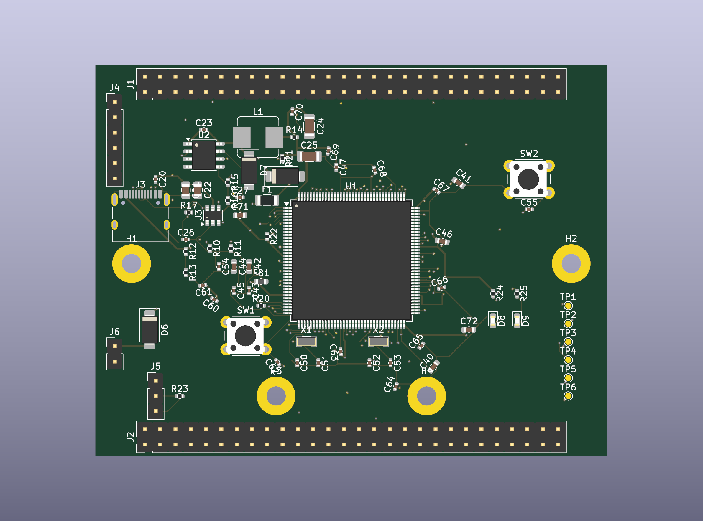
一块 STM32H743ZIT6(LQFP144, Cortex-M7 @ 480MHz)最小系统核心板,以及生成它的全自动化 EDA 流水线:
├── STM32H743ZIT6_核心板设计规格书.md   # 唯一真源:设计规格(人审输入)
├── doc/                              # 参考资料与方法论
│   ├── 方法论与流程记录.md            # 五阶段流水线方法论 + 踩坑实录
│   ├── 开源参考设计登记.md            # 参考设计链接/许可证清单
│   ├── extracted/                    # 参考 PDF 的文本提取版
│   └── *.pdf                         # 数据手册/应用笔记/官方原理图
├── kicad/                            # 全部 EDA 产物
│   ├── stm32h743_core.kicad_sch      # 原理图源文件
│   ├── stm32h743_core.kicad_pcb      # PCB 源文件(最终版)
│   ├── stm32h743_core.pdf            # 原理图 PDF
│   ├── board_all_layers.pdf          # PCB 分层图 PDF
│   ├── gerbers/                      # Gerber + Excellon 钻孔(可投板)
│   ├── pos.csv / bom.csv             # 贴片坐标 / 物料清单
│   └── drc.json                      # DRC 报告
└── tools/                            # 全部生成与检查脚本
    ├── extract_pins.py               # 引脚真源核验(符号库 ↔ 数据手册)
    ├── gen_schematic.py              # 原理图生成器
    ├── check_netlist.py              # 网表正确性门禁
    ├── sch_build.py                  # .kicad_sch S-expr 生成框架
    ├── gen_pcb.py                    # PCB 生成器(pcbnew API)
    ├── pipeline_pcb.py               # 布线/回写/DRC/制造文件编排
└── repair_pcb.py 等 # 局部补线/修复工具环境:KiCad 10(含自带 Python)、任意 Python 3.10+、Freerouting v2.4.x(获取方式见下)。
# 1. 原理图生成 + 网表门禁
python tools/gen_schematic.py
python tools/check_netlist.py          # 期望: 网表门禁全部通过

# 2. PCB 建板(含预布线种子)+ DSN 电源类编辑
"<KiCad>/bin/python.exe" tools/gen_pcb.py
python tools/pipeline_pcb.py dsn

# 3. Freerouting 无头布线(-mt 1 必须,见方法论 4.3)
python tools/pipeline_pcb.py route --max-passes 5

# 4. SES 回写 + 整区灌铜 + DRC
"<KiCad>/bin/python.exe" tools/finish_pcb.py
python tools/pipeline_pcb.py drc       # 期望: 0 error / 0 未连通

# 5. 制造文件
python tools/pipeline_pcb.py fab # Gerber/钻孔 → kicad/gerberstools/freerouting/ 不入库(约 500MB)。手动放置以下内容即可复现:
mkdir -p tools/freerouting && cd tools/freerouting
# Freerouting v2.4.1(需 Java 25)
curl -L -o freerouting.jar https://github.com/freerouting/freerouting/releases/download/v2.4.1/freerouting-2.4.1.jar
# Temurin JRE 25(国内可用清华镜像)
curl -L -o jre25.zip https://mirrors.tuna.tsinghua.edu.cn/Adoptium/25/jre/x64/windows/OpenJDK25U-jre_x64_windows_hotspot_25.0.4.1_1.zip
unzip jre25.zip| 文档 | 内容 |
|---|---|
| 设计规格书 | 电源/时钟/启动/调试/DRC 规则 + 验收清单,自动化流水线的输入契约 |
| 方法论与流程记录 | 五阶段流水线、真源链设计、踩坑实录(封装原点/约束错位/种子布线…) |
| 开源参考设计登记 | NUCLEO-H743ZI2 / WeAct 等参考设计链接与许可证 |
关键设计依据:ST AN4938(硬件开发入门)、DS12110(数据手册)、ES0392(勘误)、TI TPS54331 数据手册 §8.2 例程——均已本地化在 doc/。
kicad/drc.json)代码与设计文件以 MIT 发布。doc/ 内的 ST/TI 版权文档(数据手册/应用笔记/官方原理图)版权归原作者所有,仅作本地参考,请遵循原厂商条款使用。
| Qty | Value | Footprint | References |
|---|---|---|---|
| 15 | 100nF | C_0402_1005Metric | C43, C48, C54, C55, C60, C61, C62, C63, C64, C65, C66, C67, C68, C69, C70 |
| 4 | 100n | C_0402_1005Metric | C20, C23, C45, C47 |
| 4 | 18pF | C_0402_1005Metric | C50, C51, C52, C53 |
| 4 | M3 | MountingHole_3.2mm_M3_Pad | H1, H2, H3, H4 |
| 3 | 1uF | C_0603_1608Metric | C42, C44, C46 |
| 3 | SS34 | D_SMA | D5, D6, D7 |
| 2 | 0R | R_0402_1005Metric | R20, R21 |
| 2 | 100k | R_0402_1005Metric | R13, R23 |
| 2 | 10uF | C_0805_2012Metric | C21, C22 |
| 2 | 1k | R_0402_1005Metric | R24, R25 |
| 2 | 2.2uF | C_0603_1608Metric | C40, C41 |
| 2 | 4.7uF | C_0603_1608Metric | C71, C72 |
| 2 | 47uF | C_1206_3216Metric | C24, C25 |
| 2 | 5.1k | R_0402_1005Metric | R10, R11 |
| 2 | GPIO | PinHeader_2x28_P2.54mm_Vertical | J1, J2 |
| 1 | +3V3 | TestPoint_Pad_D1.0mm | TP1 |
| 1 | 0R | R_0805_2012Metric | R14 |
| 1 | 10.2k | R_0402_1005Metric | R15 |
| 1 | 10k | R_0402_1005Metric | R22 |
| 1 | 1nF | C_0402_1005Metric | C26 |
| 1 | 29.4k | R_0402_1005Metric | R17 |
| 1 | 3.24k | R_0402_1005Metric | R16 |
| 1 | 32.768kHz | Crystal_SMD_3215-2Pin_3.2x1.5mm | X2 |
| 1 | 3V3_SW | TestPoint_Pad_D1.0mm | TP6 |
| 1 | 47pF | C_0402_1005Metric | C27 |
| 1 | 500mA | Fuse_1206_3216Metric | F1 |
| 1 | 5VIN | PinHeader_1x02_P2.54mm_Vertical | J6 |
| 1 | 6.8uH/4A | L_Bourns_SRP7028A_7.3x6.6mm | L1 |
| 1 | 600R@100MHz | L_0603_1608Metric | FB1 |
| 1 | 68k | R_0402_1005Metric | R12 |
| 1 | 8MHz | Crystal_SMD_3215-2Pin_3.2x1.5mm | X1 |
| 1 | BOOT | PinHeader_1x03_P2.54mm_Vertical | J5 |
| 1 | BOOT0 | TestPoint_Pad_D1.0mm | TP5 |
| 1 | GND | TestPoint_Pad_D1.0mm | TP2 |
| 1 | NRST | TestPoint_Pad_D1.0mm | TP4 |
| 1 | NRST_KEY | SW_PUSH_6mm | SW1 |
| 1 | PWR_GREEN | LED_0603_1608Metric | D8 |
| 1 | STM32H743ZIT6 | LQFP-144_20x20mm_P0.5mm | U1 |
| 1 | SWD | PinHeader_1x06_P2.54mm_Vertical | J4 |
| 1 | TPS54331DDAR | SOIC-8-1EP_3.9x4.9mm_P1.27mm_EP2.29x3mm | U2 |
| 1 | USBLC6-2SC6 | SOT-23-6 | U3 |
| 1 | USB_C | USB_C_Receptacle_HRO_TYPE-C-31-M-12 | J3 |
| 1 | USER_BLUE | LED_0603_1608Metric | D9 |
| 1 | USER_KEY | SW_PUSH_6mm | SW2 |
| 1 | VCAP | TestPoint_Pad_D1.0mm | TP3 |
ramalamadingdong/pcb-agent
Design a PCB end to end with an agent: CSV source of truth, idempotent build passes, containerized KiCad+Freerouting, and checks that run on the fab output.


Deco025/rtl8367-switch
Five-port gigabit unmanaged Ethernet switch based on the Realtek RTL8367RB - 4-layer KiCad 10 design with fabrication outputs

szolotykh/kinisi-motor-controller-board
Kinisi motor controller board based on STM32F405 microcontroller


It measures 85 × 65 mm and has 4 copper layers, 1.6 mm thick.
81 parts, built around the STM32H743ZIT6, TPS54331DDAR, USBLC6-2SC6 and SS34. The full list of its parts is on this page, with links to each part's symbol and footprint where PCBKit's library has them.
From the changgeruoxiao/hagent repository on GitHub, at the commit this page was made from: the board is kicad/stm32h743_core.kicad_pcb and its schematic kicad/stm32h743_core.kicad_sch. PCBKit opens the board in the browser, with nothing to install.
Its repository publishes it under the MIT licence: you may reuse it on that licence's terms (keep the author's notice, and for a copyleft licence share your changes alike).