4 layers43.1 × 37.7 mm
Machine Controller
FinnKrass/MX-Break-In-Machine
64 Slot Break In Machine for MX Style Switches
84 parts15CERN-OHL-S-2.0

 centydev/PicoPD67
Repo for PicoPD hardware/software and documentation
PicoPD V1.2 is an open-source printed circuit board by centydev, from the centydev/PicoPD repository on GitHub, published under the MIT licence. It is a 4-layer board of 20.6 × 51.1 mm with 52 parts on 80 nets, routed with 558 tracks and 96 vias.
It is built around the RP2040, AP33772DKZ and DTC143EETL, with the MSK3419DF and TPD4E05U06DQAR among its other parts. Its parts include 19 capacitors, 16 resistors, 4 ICs, 4 diodes and 3 connectors. It belongs with the power boards and the RP2040 boards of this library.


Pico PD is a development board for USB Power Delivery development with Raspberry Pi Pico footprint. The board can help you negotiate voltage from USB PD 2.0, 3.0, and 3.1 with PPS (programable power supply) up to 5A of current at 20V max. The board feature input current/voltage/temperture reading as well as power switch to cut of the current to external devices.
Enable Serial print for debugging

To use AP33772 IC with the library, first you need to create a usbpd object. Then set up your I2C pins and start collecting the power profiles from your charger. Ensure your delay after Wire.begin() is more than 500ms for stable PDOs request. Enable pin 23 to allow VBUS pass-through.
AP33772 usbpd; // Automatically wire to Wire0

void setup()
{
  Wire.setSDA(0); // Set the correct SDA0 pin
  Wire.setSCL(1); // Set the correct SCL0 pin
  Wire.begin();
  Serial.begin(115200);
  delay(1000); 		// Delay is needed for the IC to obtain PDOs
  usbpd.begin(); 	// Start pulling the PDOs from power supply

  pinMode(25, OUTPUT); // Built in LED
  pinMode(23, OUTPUT); // Load Switch
  digitalWrite(23, HIGH); // Turn on VBUS pin

  usbpd.printPDO(); //Print out PDO to Serial port
}Common functions are:
setVoltage(int targetVoltage)       //Set voltage, unit in mV, read libary for logic flow
setMaxCurrent(int targetMaxCurrent) //Allow current limit if source has that capability
readVoltage()                       //Return voltage in mV
readCurrent()                       //Return current in mA
printPDO()                          //Print out PDOs in Serial
Set over tempearture protection
usbpd.setOTPTHR(100);               //Turn off output if NTC detect 100C or above
usbpd.setMask(OTP_EN); //Enable Over Temp Protection flagAfter flashing, the latest AP33772-CPP has been updated to auto request PDO after bootup without reconnecting the charger. Thank to @Patronics contribution.
Calling usbpd.printPDO() without Serial.begin() can soft-brick your PicoPD. Causing the IC to be non-recognizable by your computer. You will have to use PicoProbe to reflash the chip. Check out @Patronics PicoProbePCB if you would like to make a stable fixture for firmware debugging.
To enable Serial debug, there are 3 main methods:
Using USB-C Power/Data splitter (easiest): Use a USB-C Splitter that separates the USB 2.0 signal into another USB-C port. You only need USB 2.0 FullSpeed (12Mbps) for the job, but never hurts to get extra speed if needed later.
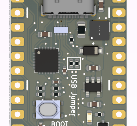
Using the provided solder pads at the back: Desolder the front "USB Jumper" resistors. They are just 2x 0 Ohm resistors that bridge between the RP2040 IC and the USB-C port. Then use a USB Type A Plug Breakout Cable, or make your own from any USB cable and connect to the existing pad at the back of PicoPD
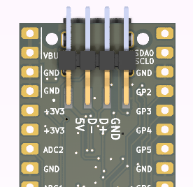
Using UART communication: Make sure you are not using GP0 and GP1 as they are reserved for I2C0 channel for AP33772 IC. Check out Youtube tutorial: Talk to Your Pico Over Serial
Open Arduino IDE, select File -> Preference

Copy this line below and place in "Aditional Boards Manager URLs" -> OK. This will allow you to pull the Earlephilhower Pico core that work with the AP33772 library.
https://github.com/earlephilhower/arduino-pico/releases/download/global/package_rp2040_index.json
From Board Manager, search for "Pico" and install the "Raspberry Pi Pico/RP2040" core by Earlephilhower

Now from Tool -> Board -> Raspberry Pi Pico/RP2040 -> Raspberry Pi Pico

Now download the latest AP33772 library as a Zip file
https://github.com/CentyLab/AP33772-Cpp
Import the AP33772 library into your Arduino IDE. Sketch -> Include library -> Add .ZIP Library ...

Now you start using the Example code in File -> Examples -> AP33772-Cpp-main. The example is ready to compile and flash on to your PicoPD.

Now you can plug in your USB-C cable with Power Delivery 2.0/3.0/3.1. If you also like to have serial print out, check out Enable Serial print for debugging.
After VSCode installation, you will need to install PlatformIO extension.

Now create a new PlatformIO project
Click "Finish"


In your new project, copy this and replace everything in platformio.ini. This is how you ask PlatformIO to compile using Earlephilhower Pico core, and enable upload via USB.
[env:pico]
platform = https://github.com/maxgerhardt/platform-raspberrypi.git
board = pico
framework = arduino
board_build.core = earlephilhower

;; If directly upload from PC
upload_protocol = picotool
Now download the latest AP33772 library as a Zip file. Unzip and place the folder in lib
https://github.com/CentyLab/AP33772-Cpp
Your lib folder should look like this

To try out example code, you copy the content inside lib/Compiled for PicoPD/PPSCycling/PPSCycling.ino, And replace everything in your src/main.cpp

Now you can plug the PicoPD to your computer via USB-C and hit the upload button. After this, you will have to connect a charger to PicoPD to see the voltage cycling example. If you also like to have serial print out, check out Enable Serial print for debugging.

| Qty | Value | Footprint | References |
|---|---|---|---|
| 11 | 100nF | Capacitor_SMD:C_0402_1005Metric | C2, C3, C4, C6, C7, C8, C9, C10, C18, C20, C21 |
| 5 | 5.1k | Resistor_SMD:R_0402_1005Metric | R1, R3, R4, R7, R16 |
| 4 | 1k | Resistor_SMD:R_0402_1005Metric | R2, R13, R14, R17 |
| 2 | 0R | Resistor_SMD:R_0402_1005Metric | R18, R19 |
| 2 | 10k | Resistor_SMD:R_0402_1005Metric | R6, R12 |
| 2 | 1u | Capacitor_SMD:C_0603_1608Metric | C15, C22 |
| 2 | 2.2uF | Capacitor_SMD:C_0402_1005Metric | C5, C11 |
| 2 | 27R | Resistor_SMD:R_0402_1005Metric | R10, R11 |
| 2 | 30pF | Capacitor_SMD:C_0402_1005Metric | C16, C17 |
| 1 | 10mR | Resistor_SMD:R_0805_2012Metric | R5 |
| 1 | 12MHz | Crystal:Crystal_SMD_3225-4Pin_3.2x2.5mm | Y1 |
| 1 | 1uF | Capacitor_SMD:C_0603_1608Metric | C12 |
| 1 | 2.2uF | Capacitor_SMD:C_0603_1608Metric | C14 |
| 1 | AP2204K-3.3 | Package_TO_SOT_SMD:SOT-23-5 | U4 |
| 1 | AP33772 | Package_DFN_QFN:QFN-24-1EP_4x4mm_P0.5mm_EP2.6x2.6mm | U1 |
| 1 | D | Diode_SMD:D_SOD-123 | D4 |
| 1 | DTC143EETL | Package_TO_SOT_SMD:SOT-416 | Q2 |
| 1 | GREEN | LED_SMD:LED_0603_1608Metric | D2 |
| 1 | MSK3419DF | AON7403:TRANS_AON7403 | Q3 |
| 1 | PICO_PINOUT | PICO_PinOut:PICO_Thru | J3 |
| 1 | RED | LED_SMD:LED_0603_1608Metric | D1 |
| 1 | RP2040 | Package_DFN_QFN:QFN-56-1EP_7x7mm_P0.4mm_EP3.2x3.2mm | U3 |
| 1 | SW_BOOT | Button LCSC:SW_PTS810_SJM_250_SMTR_LFS | SW4 |
| 1 | SW_RESET | Button LCSC:SW_PTS810_SJM_250_SMTR_LFS | SW2 |
| 1 | TPD4E05U06DQAR | IP4292CZ10-TBR:SON50P100X255X50-10N | D3 |
| 1 | Thermistor_NTC | Resistor_SMD:R_0402_1005Metric | TH1 |
| 1 | USB-Breakout | Bao_CustomFootPrint:1x4_2.54mmHorizontalSMD | J1 |
| 1 | USB_C_Receptacle | USB_C_YTC-TC16S-28:YTC-TC16S-28 | J2 |
| 1 | W25Q16JVUXIQ_TR | W25Q16JVUXIQ_TR:IC_W25Q16JVUXIQ_TR | U2 |
It measures 20.6 × 51.1 mm and has 4 copper layers, 1.61 mm thick.
52 parts, built around the RP2040, AP33772DKZ, DTC143EETL and MSK3419DF. The full list of its parts is on this page, with links to each part's symbol and footprint where PCBKit's library has them.
From the centydev/PicoPD repository on GitHub, at the commit this page was made from: the board is Hardware/PicoPD V1.2.kicad_pcb and its schematic Hardware/PicoPD V1.2.kicad_sch. PCBKit opens the board in the browser, with nothing to install.
Its repository publishes it under the MIT licence: you may reuse it on that licence's terms (keep the author's notice, and for a copyleft licence share your changes alike).
FinnKrass/MX-Break-In-Machine
64 Slot Break In Machine for MX Style Switches


open-ephys/commutator-controller
Open Ephys commutator PCB and firmware

IgorCulafic/PCBSmith
Open-source PCB design tools: KiCad workflows, automatic routing, design review and laser fabrication. Working toward plain-language circuit-to-board design.


