2 layers359.4 × 142.3 mm
Clavier drive 1
MartinDrillon/CLAVICORE
Pilotage d’un clavecin à distance grâce à un clavier ergonomique.
285 parts1

 Catsarepro21/keyboard
Its a custom keyboard! My current keyboard is pretty bad, and I thought why not make one, so i designed it.
Keeb pcb is an open-source printed circuit board by Catsarepro21, from the Catsarepro21/keyboard repository on GitHub. It is a 2-layer board of 360 × 124.3 mm with 357 parts on 207 nets, routed with 3,173 tracks and 418 vias.
It is built around the SN74LVC1T45DBVRE4, TPS2553DBVR-1 and SK6812MINI-E, with the BSS138LT1G and SS14 among its other parts. Its parts include 88 capacitors, 86 switches, 82 diodes, 12 resistors and 5 ICs. It belongs with the keyboards and input boards and the RP2040 boards of this library.


Its a custom keyboard! My current keyboard is pretty bad, and I thought why not make one, so i designed it.
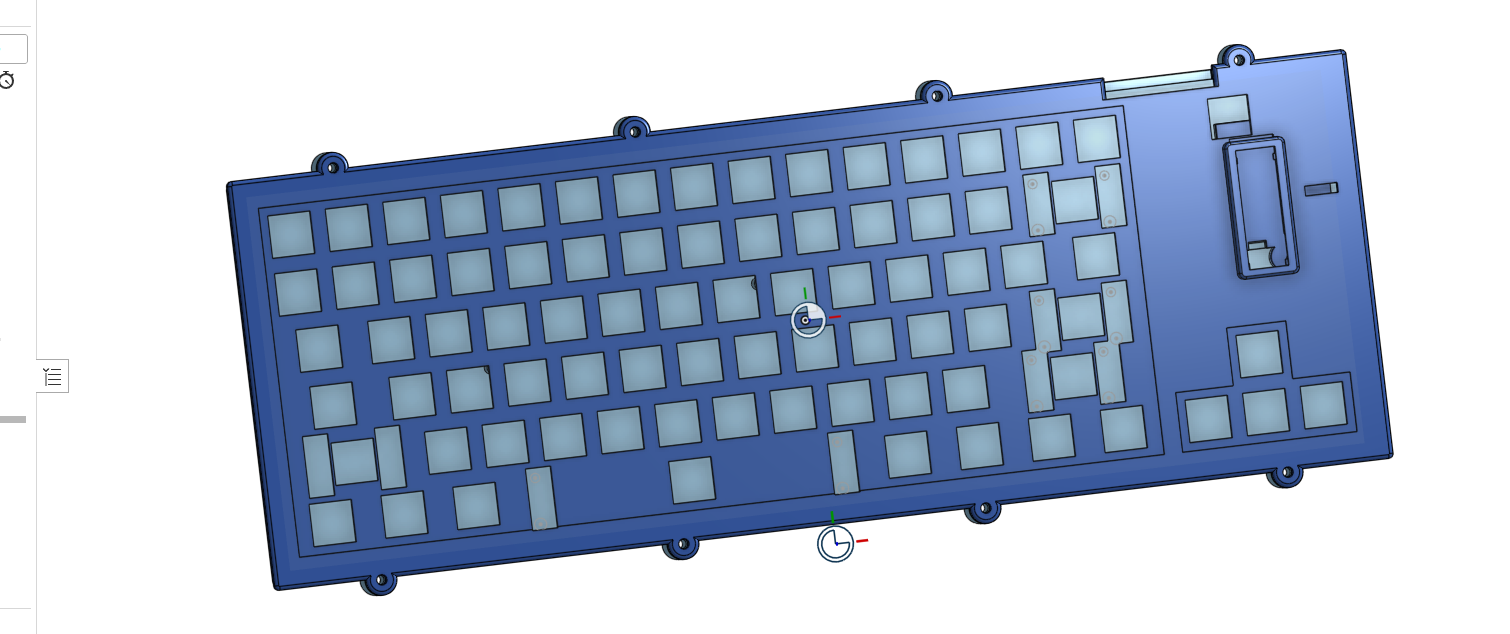
KEEB is an 80-key keyboard built around a Pico W, with USB and Bluetooth, a rechargeable battery, a volume encoder, and an OLED. It has a custom PCB and a 3D printed case with the switch plate built into the top. RGB only works when plugged into USB, which I think is fine.
Renders (Blender + Onshape):
The case and integrated switch plate:
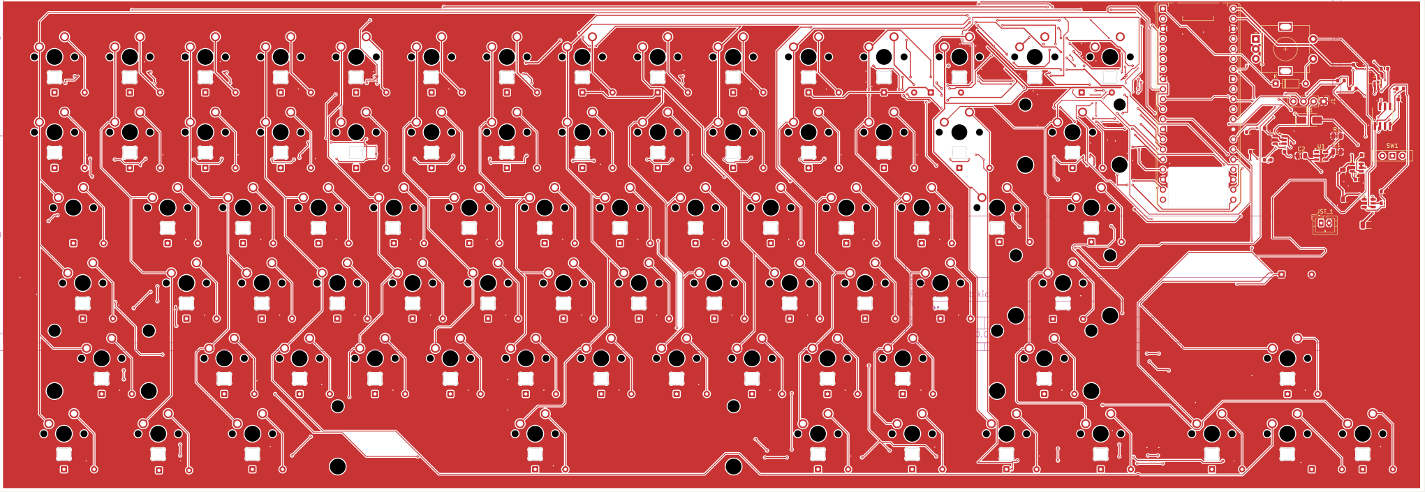
The full PCB layout:
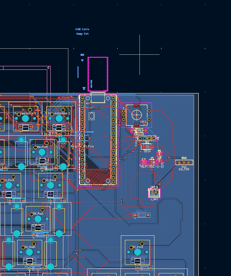
A closer look at the routing around the Pico W and controls:
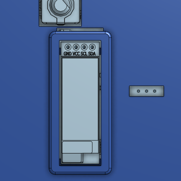
The OLED and encoder area:
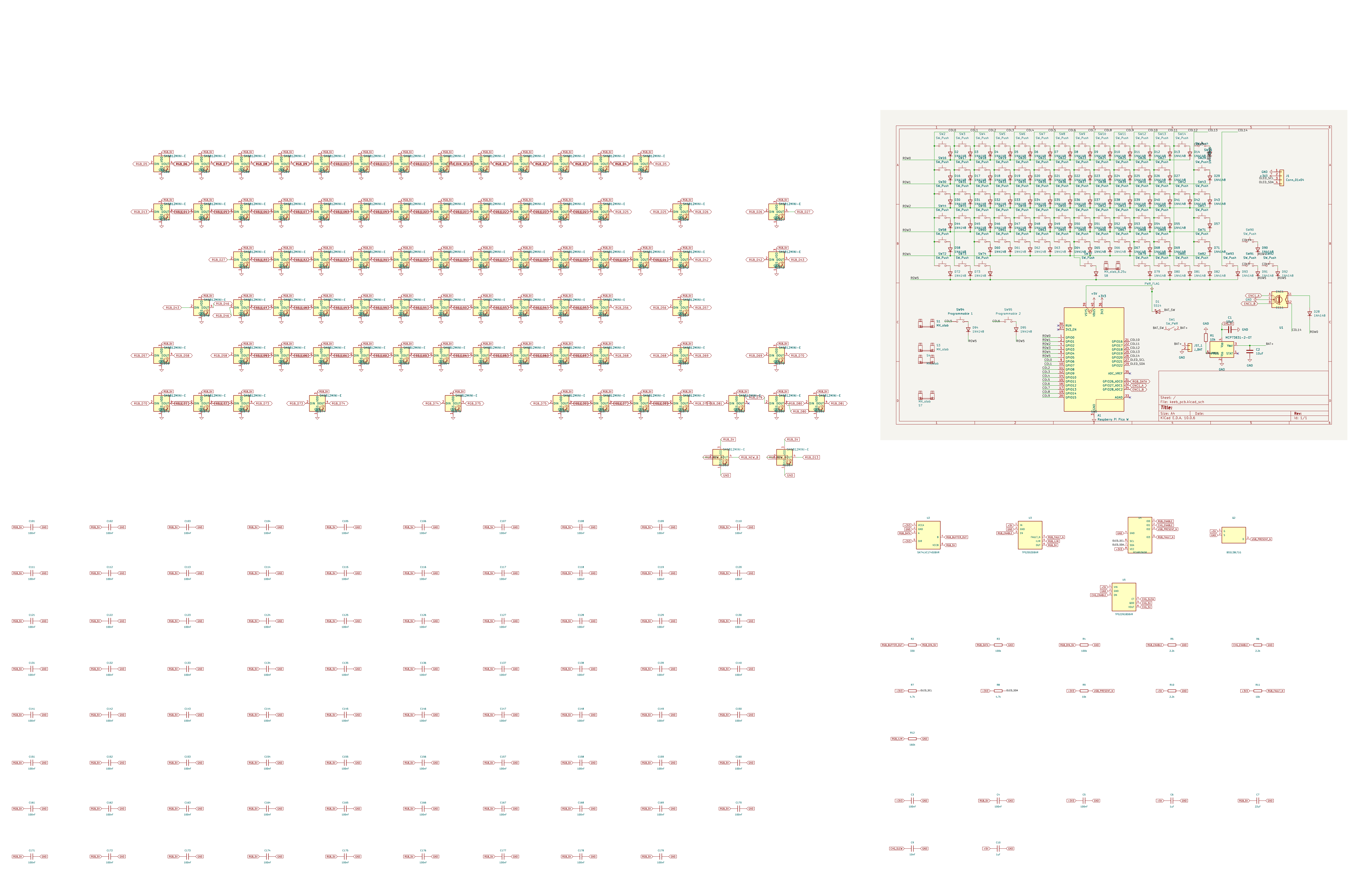
The schematic (open the image to zoom in):
If Onshape shows 403 when opened from GitHub for some reason, copy and paste this address into your browser:
https://cad.onshape.com/documents/a273834a75c8cf83eaf3eccf/w/175ac2f63e3c24ffd6632dd1/e/d788e341cf0c23216b358283The switches, diodes, encoder, and RGB are connected through the PCB. The OLED uses its included cable, with the board-side plug trimmed off and the four wires soldered directly to J1. Match the signal labels, since wire colors and connector order can vary.
PCB J1                         OLED
1  GND ----------------------- GND
2  +3V3 ---------------------- VCC
3  OLED_SCL (Pico GP21) ------- SCL / CLK
4  OLED_SDA (Pico GP22) ------- SDA / DIN

Protected 500 mAh LiPo -------- JST_1 battery connector
                               Check + and - before plugging it in.
The OLED is the Waveshare 0.91 inch SSD1306 module, using I2C at address 0x3c. Use the PCB pad numbers above, not the order the wires happen to come in.
Use the included firmware for the original Pico W (RP2040).
RPI-RP2 should show up. Copy KEEB.uf2 onto it.The firmware uses RMK, with the keymap in keyboard.toml. The encoder is mapped to volume up/down, and its push switch is mapped to mute. Vial support is enabled for changing mappings over USB.
For Bluetooth, disconnect USB, connect the battery, turn on the power switch, and look for KEEB Wireless in your computer's Bluetooth pairing menu.
The OLED code displays KEEB and USB or BAT. BAT means battery mode, not a battery percentage. RGB and charging are enabled by the current firmware after the USB connection is configured.
Helped a lot with large PCB design, wiring carefully, and just overall laying things out well. Adding Bluetooth also meant adding a battery and charger, rerouting around the antenna area, and changing the case to fit everything.
Original listed parts and PCB total: $106.13, with printing still to be priced. Check current prices and shipping before ordering.
| Part | Specification | Needed | Buy | Line cost | Link |
|---|---|---|---|---|---|
| Wireless controller | Raspberry Pi SC0918 Pico W | 1 | 1 | $6.00 | Buy |
| MX key switches | Gateron KS-3Y10B050NW-X1 | 80 | 80 | $16.00 | Buy |
| Matrix diodes | XCH 1N4148 / C7437620 | 81 | 100 | $0.91 | Buy |
| RGB LEDs | OPSCO SK6812MINI-E / C5149201 | 79 | 85 | $5.53 | Buy |
| Rotary encoder with push | Alps EC11E18244AU | 1 | 1 | $2.22 | Buy |
| Battery charger | MCP73831T-2ACI/OT | 1 | 1 | $0.78 | Buy |
| Battery isolation diode | Vishay SS14-E3/61T | 1 | 3 | $0.35 | Buy |
| Power slide switch | Wurth 450301014042, 300 mA / 24 V DC | 1 | 1 | $2.15 | Buy |
| Battery connector | JST B2B-PH-K-S(LF)(SN) | 1 | 20 | $0.71 | Buy |
| Charge-current resistor | Yageo RC0805FR-0710KL (10k, 0805) | 1 | 100 | $0.58 | Buy |
| Charger capacitors | TDK C2012X5R1V106MT000E / C415295 (10uF, 0805) | 2 | 2 | $0.52 | Buy |
| RGB data translator | TI SN74LVC1T45DBVR | 1 | 5 | $0.42 | Buy |
| RGB current limiter | TI TPS2553DBVR | 1 | 1 | $0.54 | Buy |
| Control/status expander | TI PCA9536DR | 1 | 1 | $1.56 | Buy |
| Charger load switch | TI TPS22918DBVR | 1 | 1 | $0.59 | Buy |
| USB detection MOSFET | onsemi BSS138LT1G | 1 | 10 | $0.44 | Buy |
| Local bypass capacitors | Samsung CL10B104KB8NNNC (100nF, 0603) | 82 | 100 | $0.82 | Buy |
| USB switch input capacitors | Samsung CL21B105KAFNNNE (1uF, 0805) | 2 | 10 | $0.41 | Buy |
| RGB bulk capacitor | Samsung CL31A226KAHNNNE (22uF, 1206) | 1 | 1 | $0.48 | Buy |
| Charger rise-time capacitor | Murata GRM1885C1H103JA01D (10nF, 0603) | 1 | 1 | $0.14 | Buy |
| 330 ohm LED data series | Yageo RC0603FR-07330RL (330, 0603) | 1 | 10 | $0.25 | Buy |
| 100 kohm RGB pull-downs | Yageo RC0603FR-07100KL (100k, 0603) | 2 | 10 | $0.25 | Buy |
| 2.2 kohm enables and VBUS bleed | Yageo RC0603FR-072K2L (2.2k, 0603) | 3 | 100 | $0.18 | Buy |
| 4.7 kohm I2C pull-ups to 3.3 V | Yageo RC0603FR-074K7L (4.7k, 0603) | 2 | 10 | $0.25 | Buy |
| 10 kohm status pull-ups | Yageo RC0603FR-0710KL (10k, 0603) | 2 | 100 | $0.34 | Buy |
| 160 kohm RGB current limit | Yageo RC0603FR-07160KL (160k, 0603) | 1 | 100 | $0.22 | Buy |
| OLED board-side connection | Included cable: trim plug and direct-solder four wires by signal; no header | 1 | 1 | $0.00 | Buy |
| Stabilizer kit | Fynmi black PCB screw-in kit, 4 x 2u + 1 x 6.25u | 5 | 1 | $4.09 | Buy |
| Protected LiPo battery | Adafruit 1578, 500 mAh | 1 | 1 | $7.95 | Buy |
| OLED module | Waveshare 14657, SSD1306 128 x 32 | 1 | 1 | $6.99 | Buy |
| Encoder knob | Adafruit 5093 | 1 | 1 | $0.75 | Buy |
| USB data cable | Cvilux DH-20M50055 | 1 | 1 | $1.58 | Buy |
| Keycap set | 129-key white pudding PBT, OEM profile, MX stems; required key sizes covered | 80 | 1 | $10.22 | Buy |
| Case inserts | XHHD SZTB1150 / C51939019, M3 x 4.5 x 5 mm | 10 | 20 | $0.47 | Buy |
| Case screws | M3 50pcs / 8mm ISO7380 button-head | 10 | 50 | $1.75 | Buy |
| Adhesive feet | Adafruit 550, pack of four approx 8 × 4 mm bumpers | 4 | 1 | $0.95 | Buy |
| Case print | Printed bottom, top with integrated MX switch plate, removable battery cover | 3 | 1 | Printing Legion? | Buy |
| Controller mounting pins | BOOMELE 2.54-1*40P / C2337 | 1 | 5 | $0.80 | Buy |
| Battery retention/insulation | JSZ-007 polyimide tape, 30 mm x 33 m x 0.05 mm | 1 | 1 | $2.34 | Buy |
| PCB | 359.95 x 124.25 mm; 2 layers; 1.6 mm FR4; green; HASL; no optional paid production-file confirmation | 1 | 5 | $25.60 | Buy |
| AliExpress shipping | White keycaps and Fynmi stabilizers together; cart showed free shipping on 13 October 2026 | 1 | 1 | $0.00 | Buy |
| Qty | Value | Footprint | References |
|---|---|---|---|
| 82 | 100nF | Capacitor_SMD:C_0603_1608Metric | C101, C102, C103, C104, C105, C106, C107, C108, C109, C110, C111, C112, C113, C114, C115, C116 +66 |
| 81 | 1N4148 | Diode_THT:D_DO-35_SOD27_P7.62mm_Horizontal | D2, D10, D11, D12, D13, D14, D15, D16, D17, D18, D19, D20, D21, D22, D23, D24 +65 |
| 79 | SK6812MINI-E | LED_SMD:LED_SK6812MINI-E_3.2x2.8mm_P1.5mm_ReverseMount | RGB1, RGB2, RGB10, RGB11, RGB12, RGB13, RGB14, RGB15, RGB16, RGB17, RGB18, RGB19, RGB20, RGB21, RGB22, RGB23 +63 |
| 77 | SW_Push | KeyboardVerified:SW_MX_1u | SW2, SW10, SW11, SW13, SW14, SW15, SW16, SW17, SW18, SW19, SW20, SW21, SW22, SW23, SW24, SW25 +61 |
| 4 | MX_stab | PCM_marbastlib-mx:STAB_MX_2u | S1, S3, S4, S7 |
| 3 | 2.2k | Resistor_SMD:R_0603_1608Metric | R5, R6, R10 |
| 2 | 100k | Resistor_SMD:R_0603_1608Metric | R3, R4 |
| 2 | 10k | Resistor_SMD:R_0603_1608Metric | R9, R11 |
| 2 | 10uF | Capacitor_SMD:C_0805_2012Metric | C1, C2 |
| 2 | 1uF | Capacitor_SMD:C_0805_2012Metric | C6, C10 |
| 2 | 4.7k | Resistor_SMD:R_0603_1608Metric | R7, R8 |
| 1 | 10k | Resistor_SMD:R_0805_2012Metric | R1 |
| 1 | 10nF | Capacitor_SMD:C_0603_1608Metric | C9 |
| 1 | 160k | Resistor_SMD:R_0603_1608Metric | R12 |
| 1 | 22uF | Capacitor_SMD:C_1206_3216Metric | C7 |
| 1 | 330 | Resistor_SMD:R_0603_1608Metric | R2 |
| 1 | BSS138LT1G | Package_TO_SOT_SMD:SOT-23 | Q2 |
| 1 | Conn_01x04 | Connector_PinHeader_2.54mm:PinHeader_1x04_P2.54mm_Vertical | J1 |
| 1 | EC11 | Rotary_Encoder:RotaryEncoder_Alps_EC11E-Switch_Vertical_H20mm | ENC1 |
| 1 | J_BAT | Connector_JST:JST_PH_B2B-PH-K_1x02_P2.00mm_Vertical | JST_1 |
| 1 | MCP73831-2-OT | Package_TO_SOT_SMD:SOT-23-5 | U1 |
| 1 | MX_stab_6.25u | PCM_marbastlib-mx:STAB_MX_6.25u | S8 |
| 1 | PCA9536DR | Package_SO:SOIC-8_3.9x4.9mm_P1.27mm | U4 |
| 1 | Programmable 1 | KeyboardVerified:SW_MX_1u | SW94 |
| 1 | Programmable 2 | KeyboardVerified:SW_MX_1u | SW95 |
| 1 | Raspberry Pi Pico W | KeyboardVerified:RaspberryPi_Pico_Common_THT_Bare_W | A1 |
| 1 | SN74LVC1T45DBVR | Package_TO_SOT_SMD:SOT-23-6 | U2 |
| 1 | SS14 | Diode_SMD:D_SMA | D1 |
| 1 | SW_PWR | Button_Switch_THT:SW_Slide-03_Wuerth-WS-SLTV_10x2.5x6.4_P2.54mm | SW1 |
| 1 | SW_Push | KeyboardVerified:SW_MX_1u_RGB_Clearance | SW12 |
| 1 | TPS22918DBVR | Package_TO_SOT_SMD:SOT-23-6 | U5 |
| 1 | TPS2553DBVR | Package_TO_SOT_SMD:SOT-23-6 | U3 |
It measures 360 × 124.3 mm and has 2 copper layers, 1.6 mm thick.
357 parts, built around the SN74LVC1T45DBVRE4, TPS2553DBVR-1, SK6812MINI-E and BSS138LT1G. The full list of its parts is on this page, with links to each part's symbol and footprint where PCBKit's library has them.
From the Catsarepro21/keyboard repository on GitHub, at the commit this page was made from: the board is pcb/keeb_pcb.kicad_pcb and its schematic pcb/keeb_pcb.kicad_sch. PCBKit opens the board in the browser, with nothing to install.
Its repository states no licence, so its author keeps all rights: ask Catsarepro21 before reusing the design.
MartinDrillon/CLAVICORE
Pilotage d’un clavecin à distance grâce à un clavier ergonomique.

AxelMcKenna/AFX-1000
RMX-1000-inspired effects processor for macOS, AU and VST3, built on a shared C++20 engine. Standalone Daisy Seed 3 hardware with two main PCBs and a custom housing is in development.

dephekt/dosing-pump-hardware
Open schematics and design files for a computer controlled nutrient dosing system


Takingo/Mypcb35
OmniCircuit AI is a local proof of concept for an autonomous PCB/PCBA design and manufacturing suite. The current implementation focuses on the ESP32-S3 + DWM3000 UWB Anchor example and establishes the architecture for:


