2 layers45.2 × 34.8 mm

 catinella/mbElectricalSystem
Generic Motorbike Electrical System
MbElectricalSystem is an open-source printed circuit board by catinella, from the catinella/mbElectricalSystem repository on GitHub. It is a 2-layer board of 112.9 × 63.7 mm with 125 parts on 113 nets, routed with 1,535 tracks and 188 vias.
It is built around the ESP32-S2-DEVKITM-1, L7805 and BC817, with the TPCA8120,L1Q(CM, BC807 and PMEG40T30ERX among its other parts. Its parts include 46 resistors, 23 transistors, 4 diodes, 2 capacitors and 2 ICs. It belongs with the ESP32 boards of this library.


| Files/Directories | Description |
|---|---|
| pcb-c.kicad_sch | Electric symbolic scheme |
| pcb-c.kicad_pcb | PCB |
(*) This project is covered by the GPL-3. Please, read that file for further information
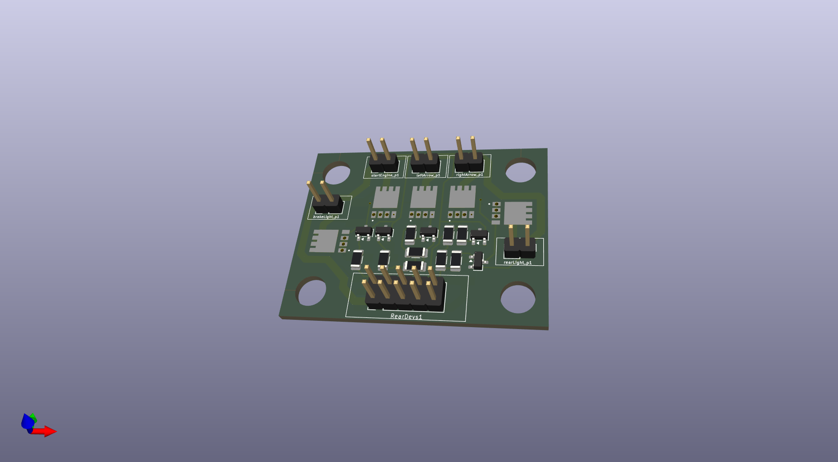
This folder contains all files you need to build and/or modify the PCB placed in the rear side of the (DR350) motorbike. This circuit is a small power stage for the rear light indicators, stop light, and position light. Because all lights are available in LED format, the power stage is set to provide maximum 500mA (6W) per device.
In order to fit this device in the DR350 rear size, I have tried to reduce the required space as much as possible. Also for this reason, normal fuses have been replaced by MSMF050 PTC Resettable Fuses.
All the power stage's outputs are equivalent but one is dedicated to the motorbike's starter relay. This relay type can be a big one, often. So, a fly-back diode is very important. For this reason I have used a M7 Rectifiers Diode.
The following images shows you the PCB shape it should be at the end
| Qty | Value | Footprint | References |
|---|---|---|---|
| 19 | 100K | Resistor_SMD:R_1206_3216Metric | R1, R5, R13, R14, RA1, RA15, RA16, RA17, RA18, RA19, RA20, RA22, RA23, RA24, RA25, RA27 +3 |
| 13 | 10K | Resistor_SMD:R_1206_3216Metric | R2, R9, RA2, RA9, RA10, RA11, RA12, RA13, RA37, RA38, RA40, RA46, RA49 |
| 11 | BC817 | Package_TO_SOT_SMD:SOT-23 | Q2, Q4, Q8, Q9, Q10, Q11, Q13, Q14, Q15, Q17, Q19 |
| 11 | Conn_01x02 | Connector_PinHeader_2.54mm:PinHeader_1x02_P2.54mm_Vertical | addLights1, Decomp_1, DownLight_p1, engReadyLed1, extpwr1, KeySW1, leftArrow_p1, LightOnOff_sw1, powerOFF1, rearDevsPwr1, rightArrow_p1 |
| 9 | 1K | Resistor_SMD:R_1206_3216Metric | R3, R4, R6, RA14, RA42, RA43, RA44, RA48, RA51 |
| 7 | 5K | Resistor_SMD:R_1206_3216Metric | RA30, RA31, RA32, RA33, RA34, RA35, RA36 |
| 7 | TPCA8120,L1Q | TPCA80120:TPH4R003NLL1Q | Q3, Q5, Q6, Q7, Q12, Q16, Q18 |
| 6 | 0 | Resistor_SMD:R_1206_3216Metric | RA3, RA4, RA5, RA6, RA7, RA8 |
| 6 | Conn_01x01 | Connector_Wire:SolderWire-1sqmm_1x01_D1.4mm_OD2.7mm | addLight_p2, GND3, GND4, GND5, Horn_p2, UpLight_p2 |
| 5 | BC807 | Package_TO_SOT_SMD:SOT-23 | Q1, Q20, Q22, Q23, Q24 |
| 4 | Conn_01x02 | Connector_JST:JST_VH_B2P-VH-FB-B_1x02_P3.96mm_Vertical | addLight_p1, Battery1, Horn_p1, UpLight_p1 |
| 4 | PMEG40T30ER | Diode_SMD:Nexperia_CFP3_SOD-123W | D1, D2, D3, flyback-1 |
| 3 | 33K | Resistor_SMD:R_1206_3216Metric | R10, R11, R12 |
| 2 | 10K | Potentiometer_THT:Potentiometer_Bourns_3296W_Vertical | RV1, RV2 |
| 2 | 15K | Resistor_SMD:R_1206_3216Metric | R7, R8 |
| 2 | Conn_01x08 | Connector_PinHeader_2.54mm:PinHeader_1x08_P2.54mm_Vertical | leftCtrls_conn1, RearDevs1 |
| 2 | MF-MSMF050-2 | MSMF:FUSE_F050-2 | F1, F2 |
| 1 | 10k | Resistor_SMD:R_1206_3216Metric | RA21 |
| 1 | 10uF | Capacitor_THT:CP_Radial_D6.3mm_P2.50mm | C1 |
| 1 | 20K | Resistor_SMD:R_1206_3216Metric | RA29 |
| 1 | C_Polarized_Small | Capacitor_THT:CP_Radial_D8.0mm_P2.50mm | C2 |
| 1 | Conn_01x03 | Connector_PinHeader_2.54mm:PinHeader_1x03_P2.54mm_Vertical | koso-1 |
| 1 | Conn_01x04 | Connector_PinHeader_2.54mm:PinHeader_1x04_P2.54mm_Vertical | Key-locker-1 |
| 1 | Conn_01x06 | Connector_PinHeader_2.54mm:PinHeader_1x06_P2.54mm_Vertical | rightCtrls_conn1 |
| 1 | Conn_02x05_Counter_Clockwise | Connector_PinHeader_2.54mm:PinHeader_2x05_P2.54mm_Vertical | LEDs_conn1 |
| 1 | ESP32-S2-DevKitM | esp32_dk:ESP32-S2-DevKitM | U1 |
| 1 | HK19F-DCxxV-SHC | Relay_THT:Relay_DPDT_Finder_30.22 | K1 |
| 1 | L7805 | Package_TO_SOT_THT:TO-220-3_Vertical | U2 |
| 1 | config | Button_Switch_THT:SW_DIP_SPSTx02_Slide_6.7x6.64mm_W7.62mm_P2.54mm_LowProfile | SW1 |
It measures 112.9 × 63.7 mm and has 2 copper layers, 1.6 mm thick.
125 parts, built around the ESP32-S2-DEVKITM-1, L7805, BC817 and TPCA8120,L1Q(CM. The full list of its parts is on this page, with links to each part's symbol and footprint where PCBKit's library has them.
From the catinella/mbElectricalSystem repository on GitHub, at the commit this page was made from: the board is PCB/main.kicad_pcb and its schematic PCB/main.kicad_sch. PCBKit opens the board in the browser, with nothing to install.
Its repository states no licence, so its author keeps all rights: ask catinella before reusing the design.


stefanskotte/webadf
Web-based Amiga ADF library that mounts disks to a Gotek over WiFi

runger1101001/SimpleFOCNano
A small BLDC driver shield in Arduino Nano form-factor.