Skip to the content
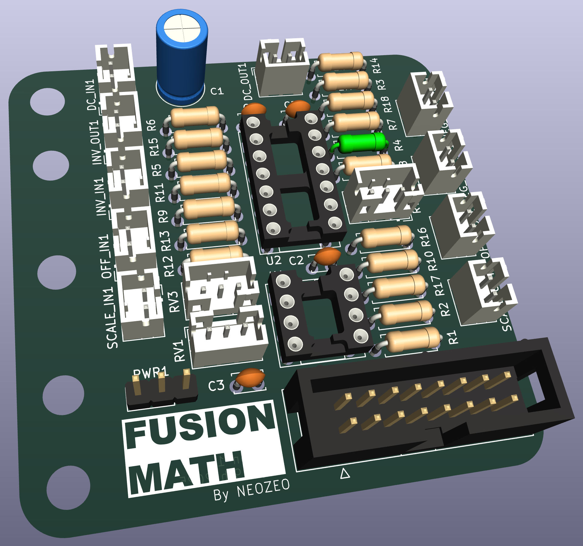
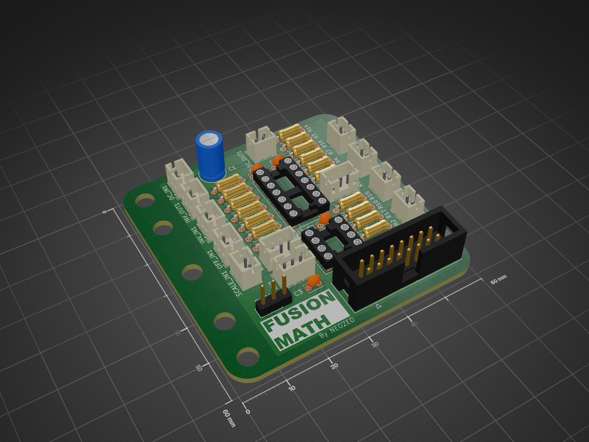
2 layers60 × 60 mmMath Module, the printed circuit board in 3D

DIY analog modular synth

Size
60 × 60 mm
Copper layers
2
Thickness
1.6 mm
Parts
40
Nets
31
Pads
116
Tracks, vias
140, 0
Pours
1
Routed
Yes
KiCad
KiCad 8.0 (file 20240108)
Created
17 Jun 2024
Updated
1 Aug 2025

Overview

Math Module is an open-source printed circuit board by carl-becker, from the carl-becker/fusion-core repository on GitHub. It is a 2-layer board of 60 × 60 mm with 40 parts on 31 nets, routed with 140 tracks and 0 vias.

It is built around the TL072. Its parts include 18 resistors, 5 capacitors, 2 ICs and 1 connector.
Main components

1

README

README.md

FUSION CORE (synthesizer)

Goal

  • Get to know delicious circuits (experimenting a lot)

  • Use them in crude ways to generate sounds

  • Learn how to design circuits & professionally manufacture them with KiCad

  • Learn whats possible with analog circuits and what's not

  • Have a lot of fun without the need of programming

  • Get an overview of electronic parts out there

  • Manage a big project

  • Make ambient dub techno at the end lol

Sound samples

  • Can be found under ./Sounds

Resources

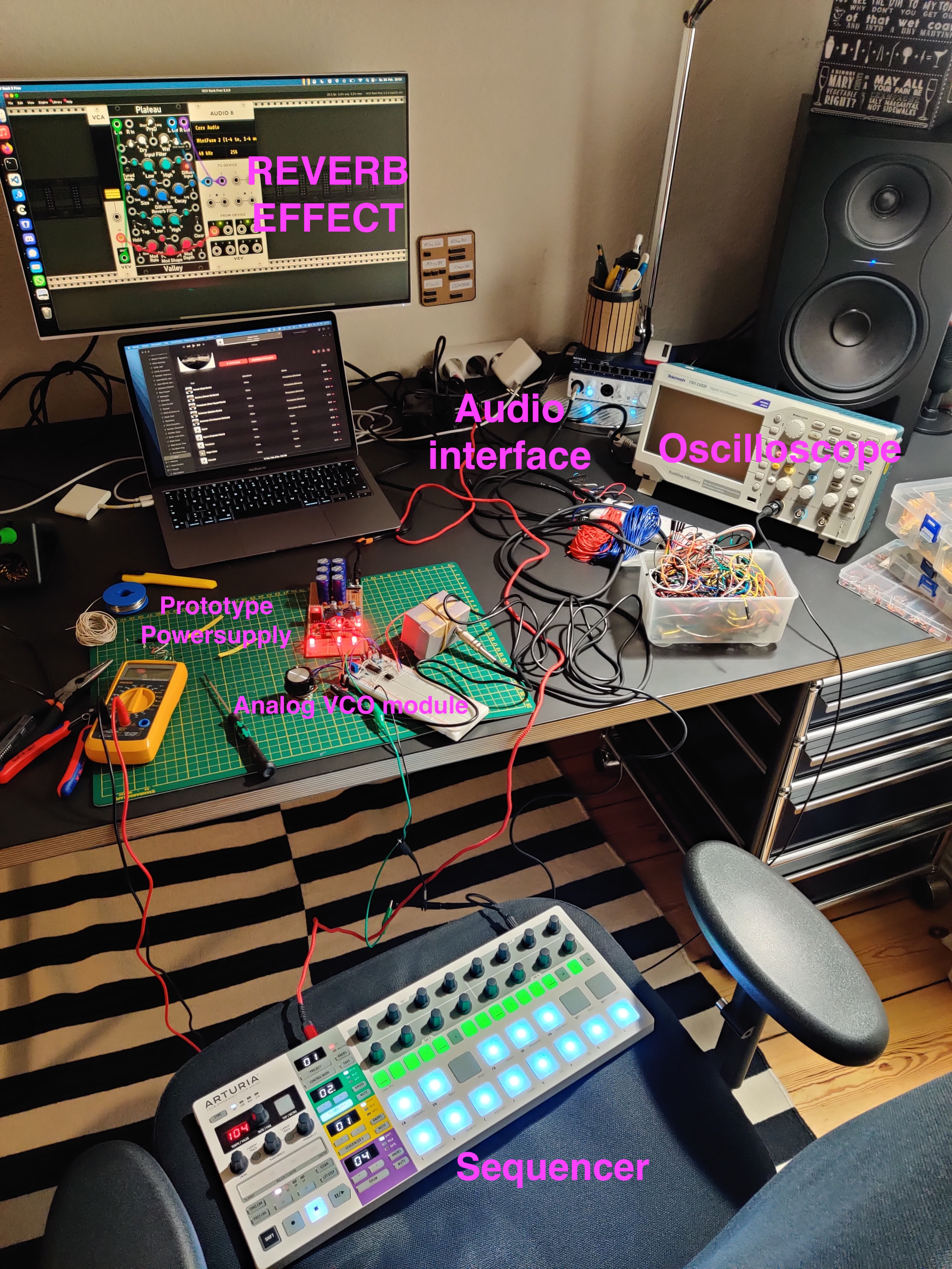
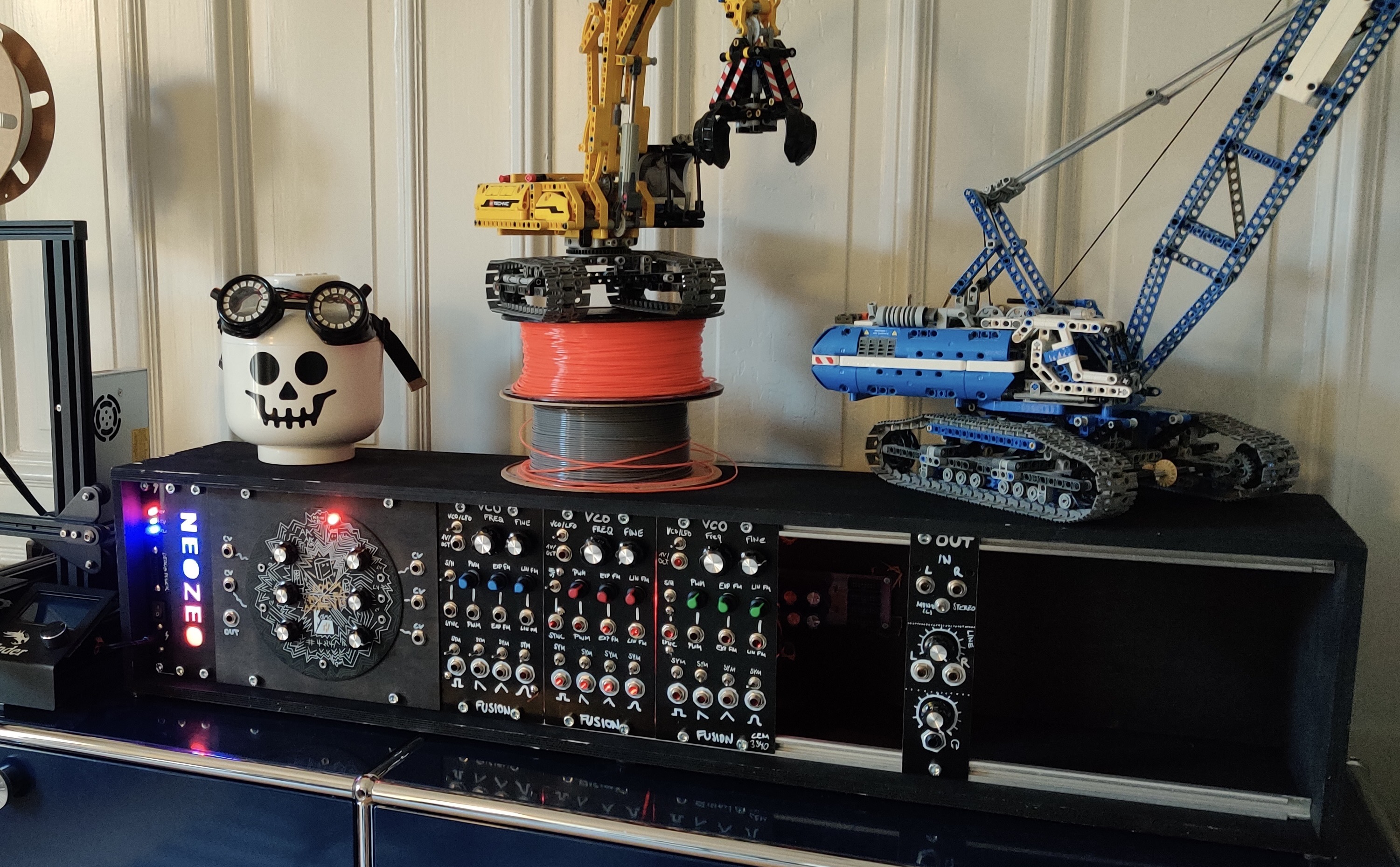
Nice shots from June 17th 2024 onwards

Obviously go to Look Mum no Computer concert!

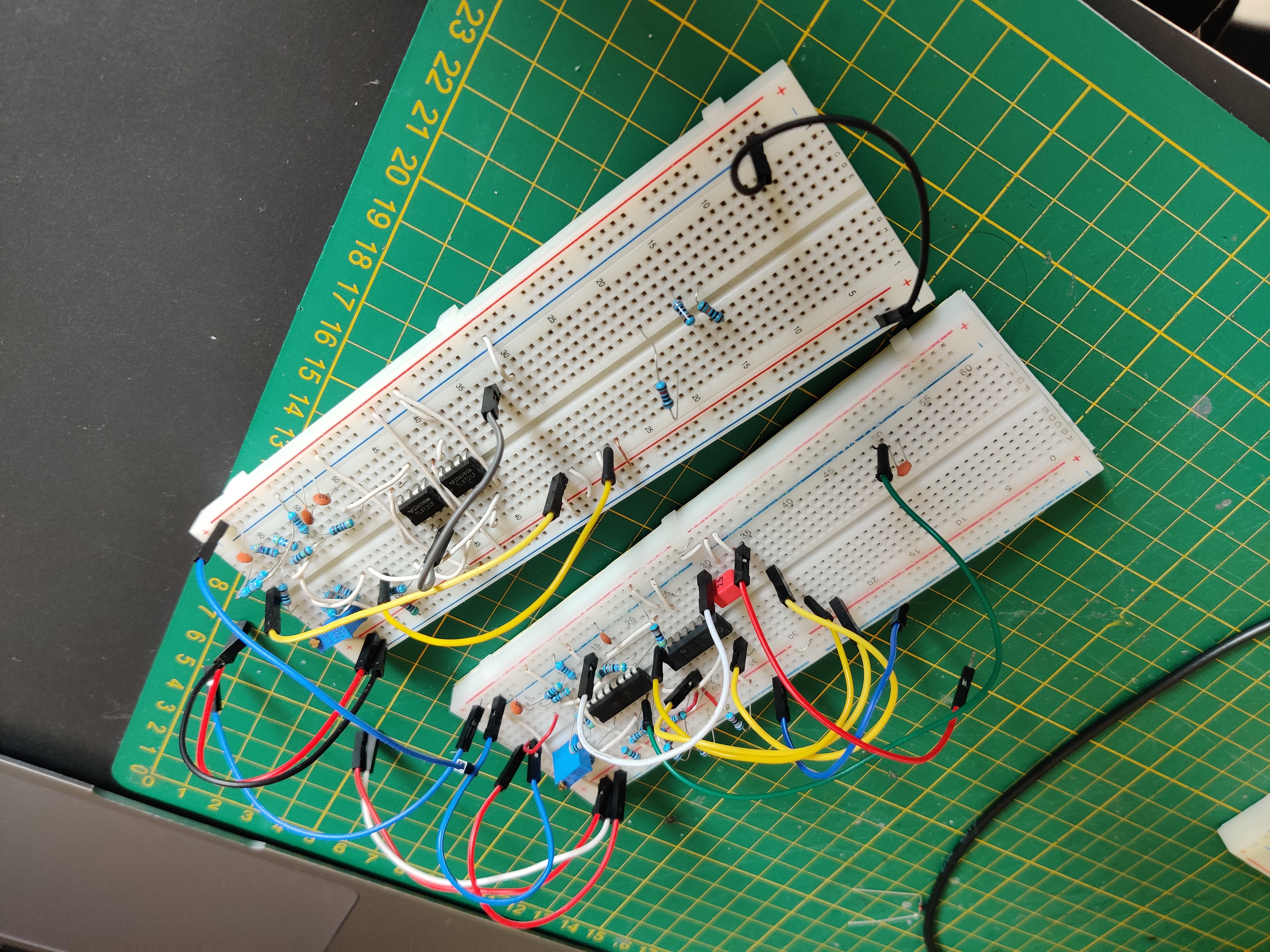
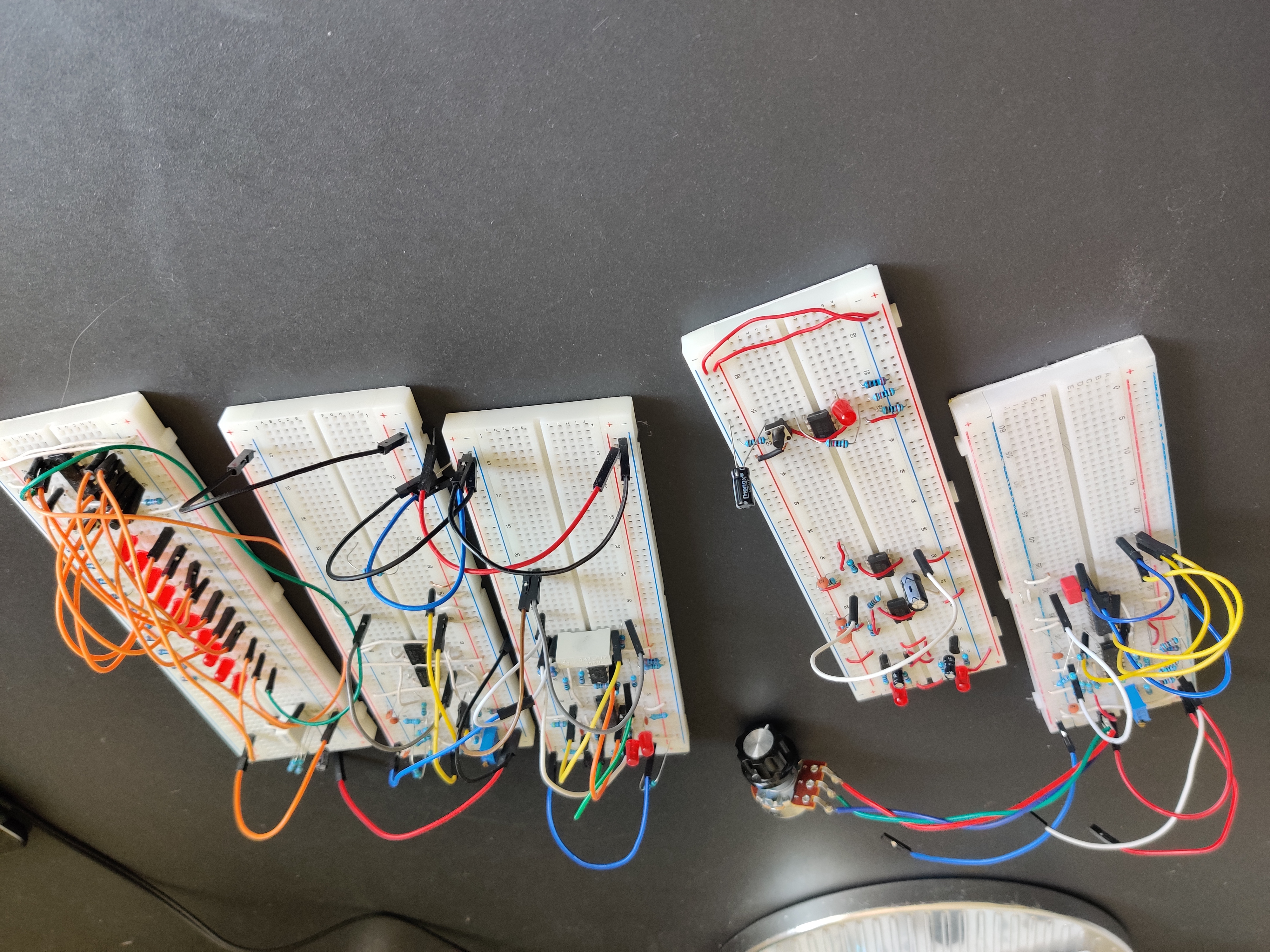
Test circuits with chaotic wiring
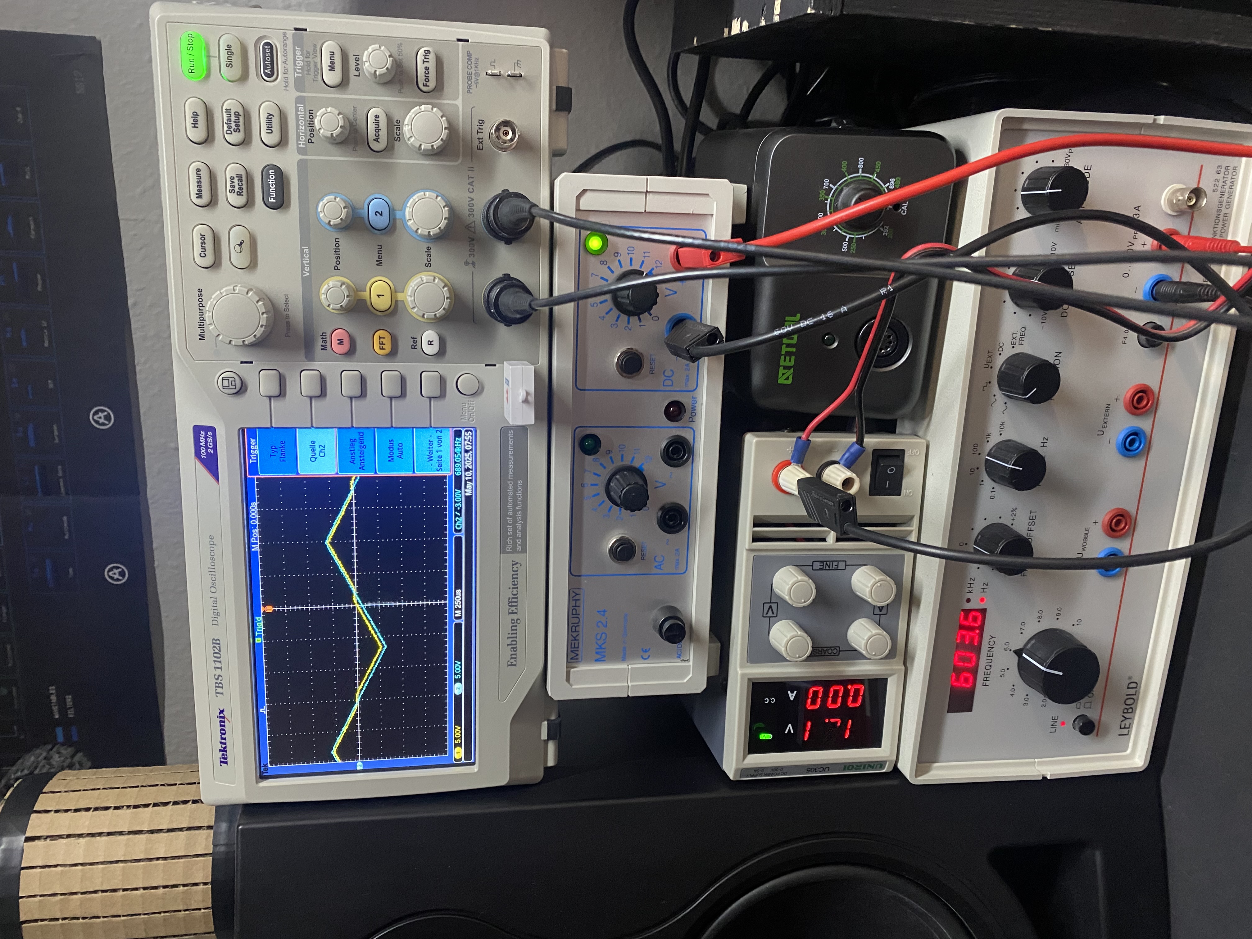
Gather lab devices (frequency generator & oscilloscope are from student research center)
Design some PCBs
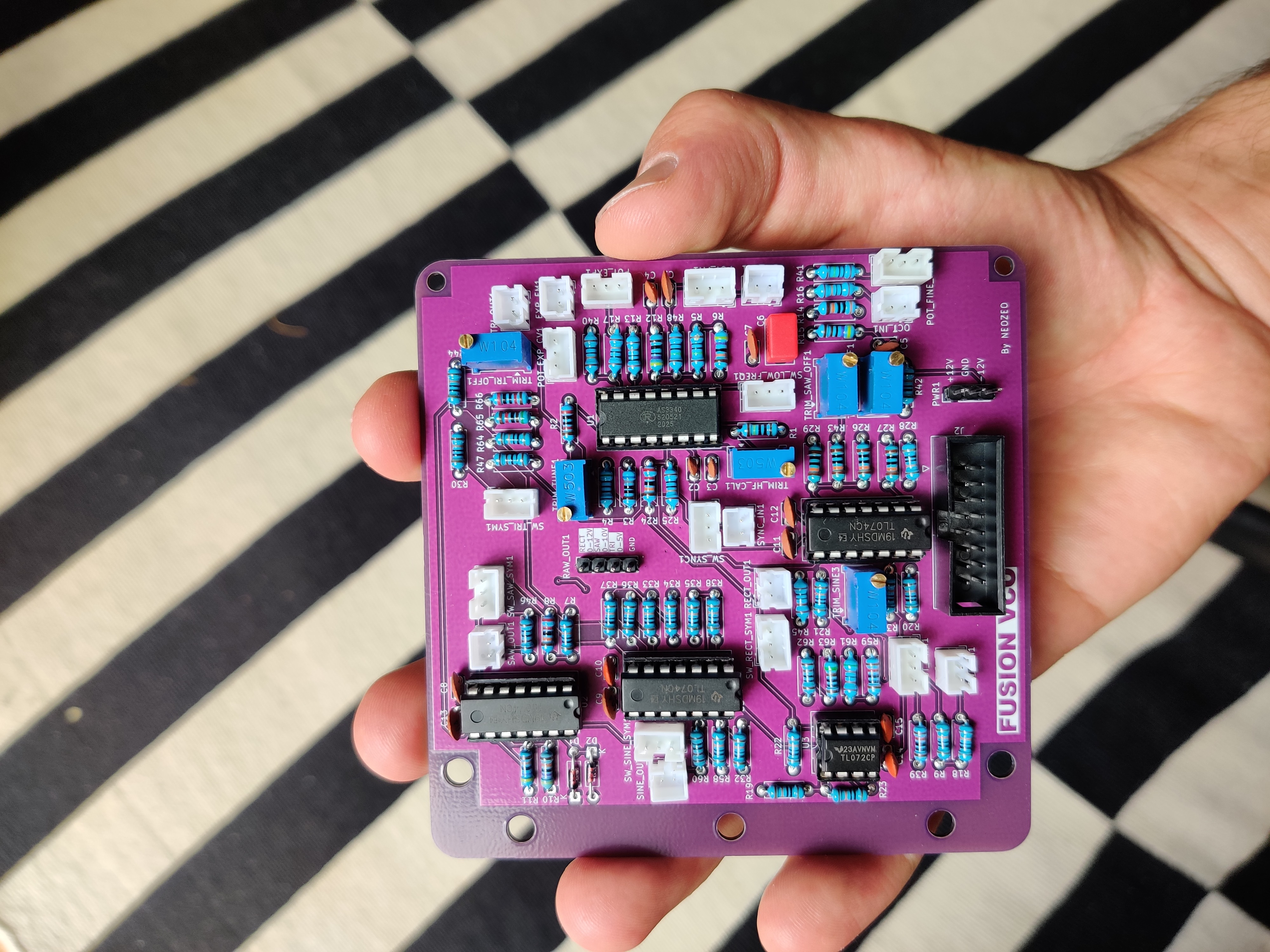
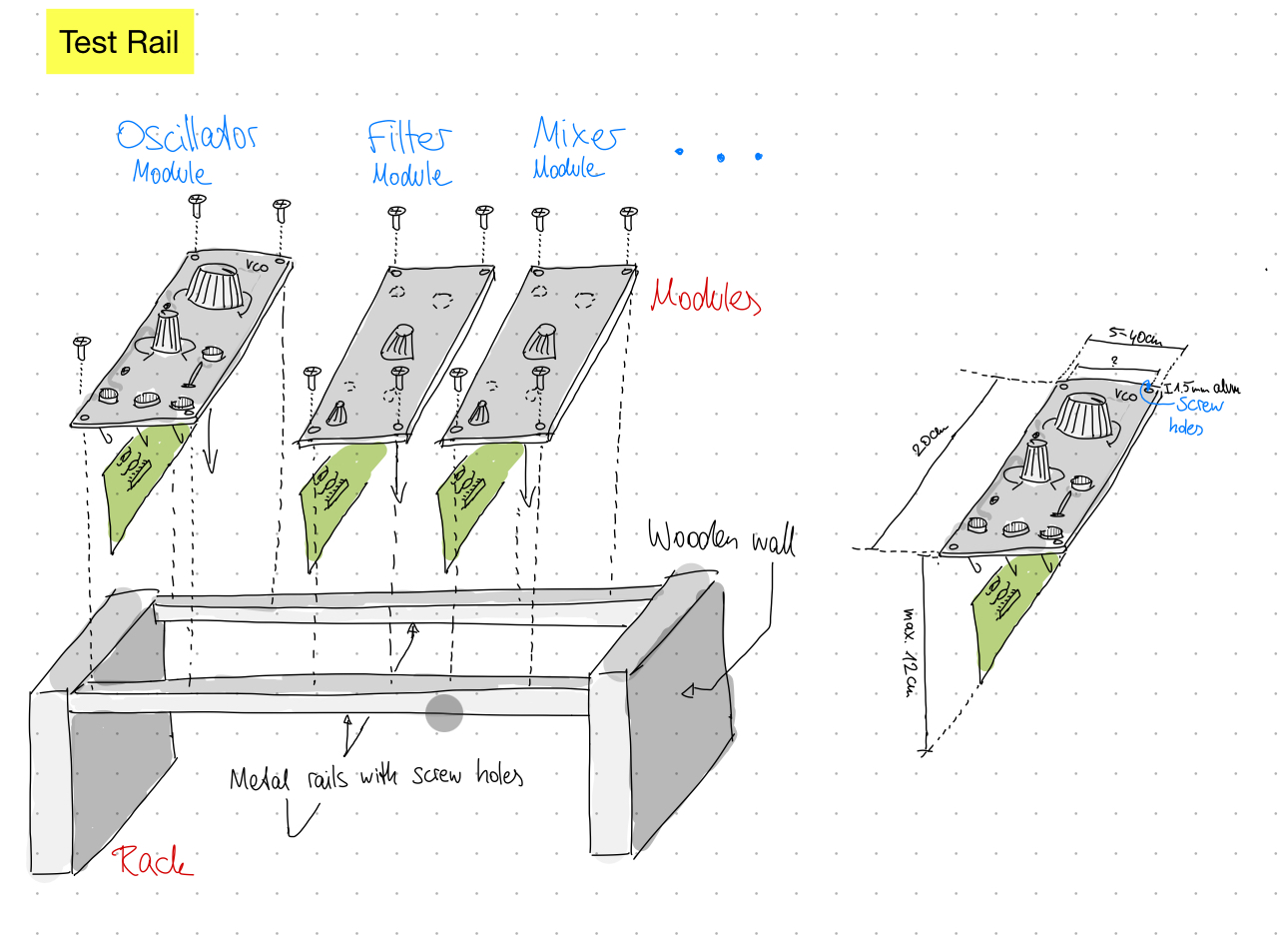
Draw some fancy ideas
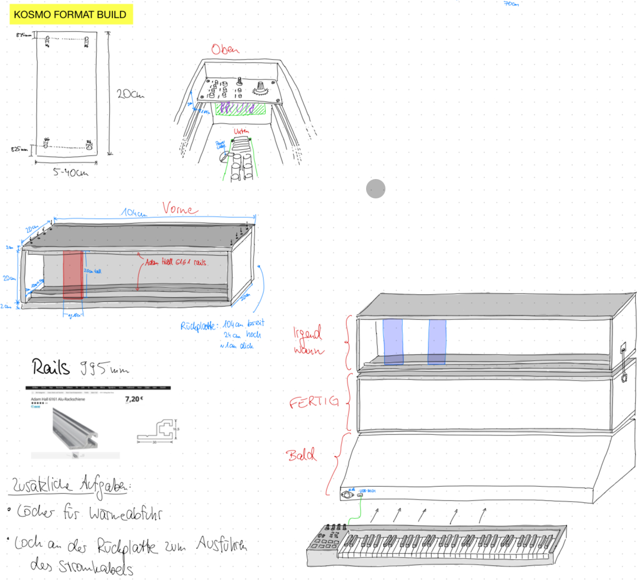
Meet with friends to build a fancy case
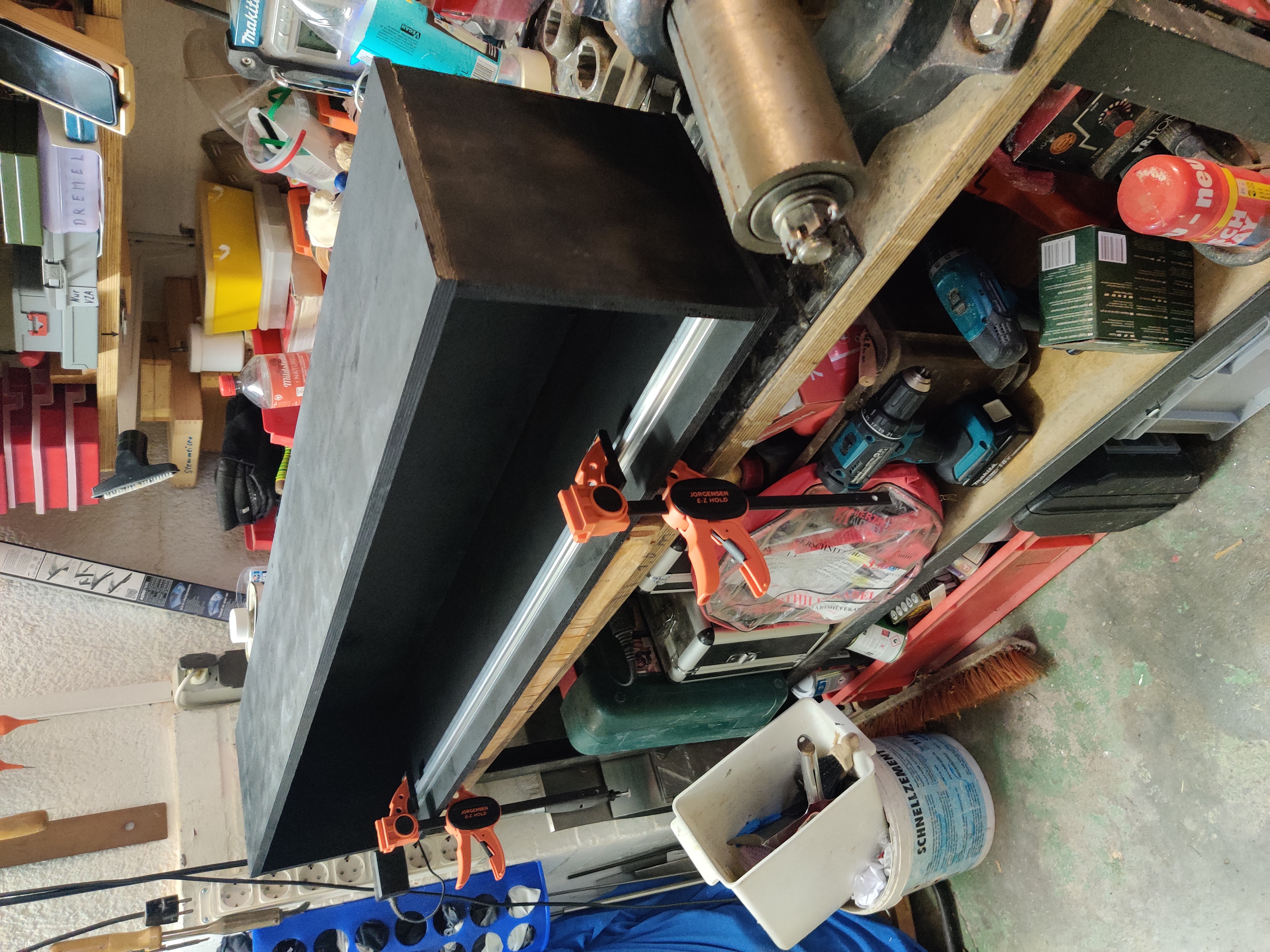
Having fun with nice dark & cozy athmosphere
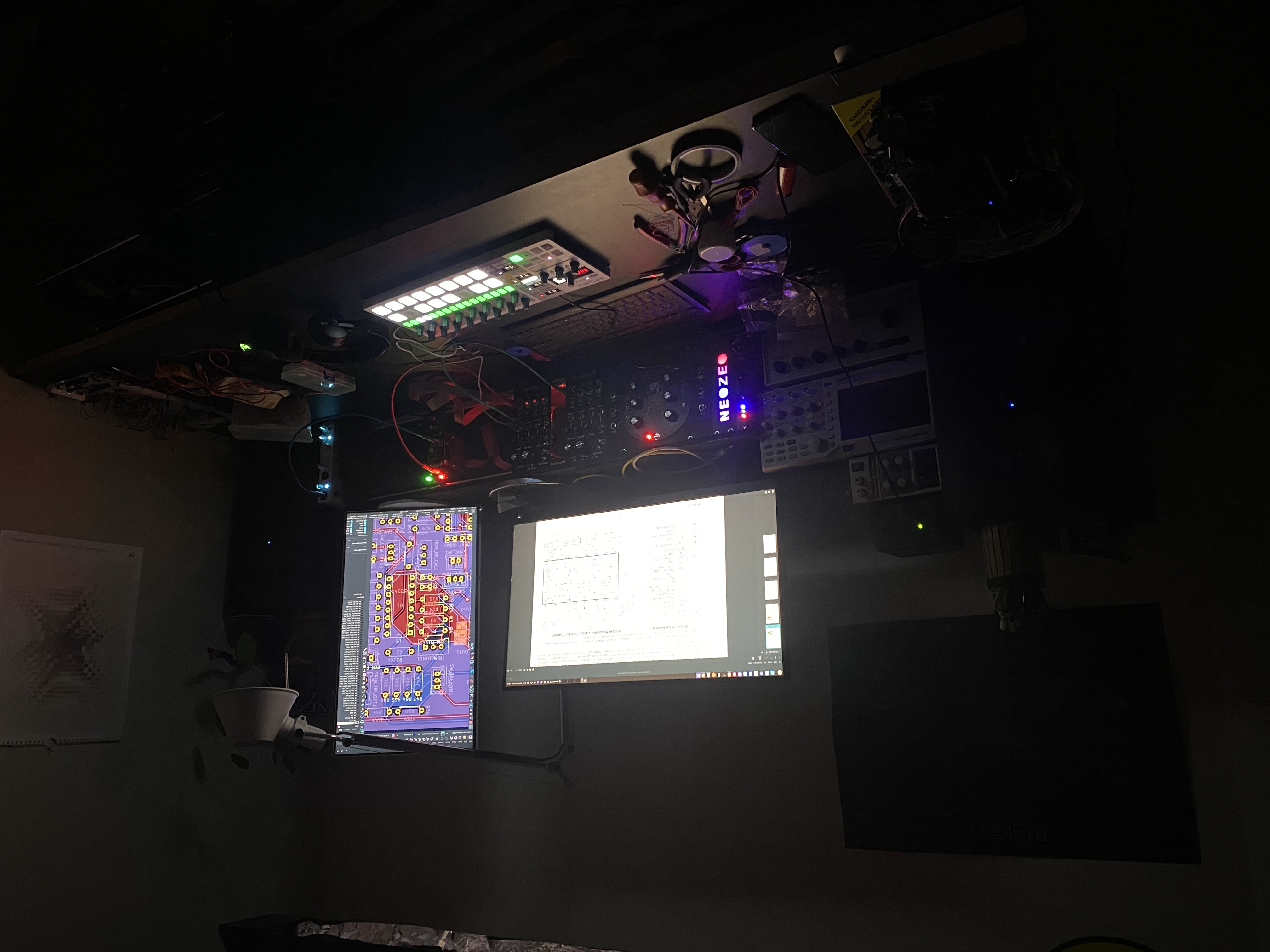
What is this repo for?

  • Contains my development files
  • Contains some notes, but definitely not a tutorial to rebuild this on your own
  • Contains some insights on what I did (this is still no complete log)
  • The chapters in the following may not be in chronological order

Module Specifications

see https://sdiy.info/wiki/Kosmo for more info

Front Plate Dimensions

  • 20cm height, variable width (KOSMO Format)
  • aluminium front plates with ~1.5mm thickness (no 3D-Printing, it takes too long, is no fun and is not that stable)
  • spray front panels black and use white edding and white sharp fineliner from the art shop to draw the ui

Power

  • ±12V, +5V
  • using official Eurorack 16Pin Plugs & Sockets with same pinout (CV & Gate pins are not used)

Signals

  • Input impedance: 100k (0.1mA @ 10V)

  • Output impedance: 1k (10mA @ 10V)

  • Max. ±10V (~ ±5V for audio signals)

  • 0V-10V for envelopes

  • -10V-0V for inverted envelopes

  • 1V/oct for Pitch/Freq. Control

  • 0V or ~5V for Gate signals

Chapter 1: Buy buy buy

  • E-Books from Make
  • The Art of Electronics
  • A lot of different parts from
    • Mouser, Reichelt
    • Aliexpress
    • Thomann
    • ElectricDruid (for old analog chips)

-> The first order cost me around 700 euros in sum, I felt reallly excited, but also under pressure, whether my plan goes well

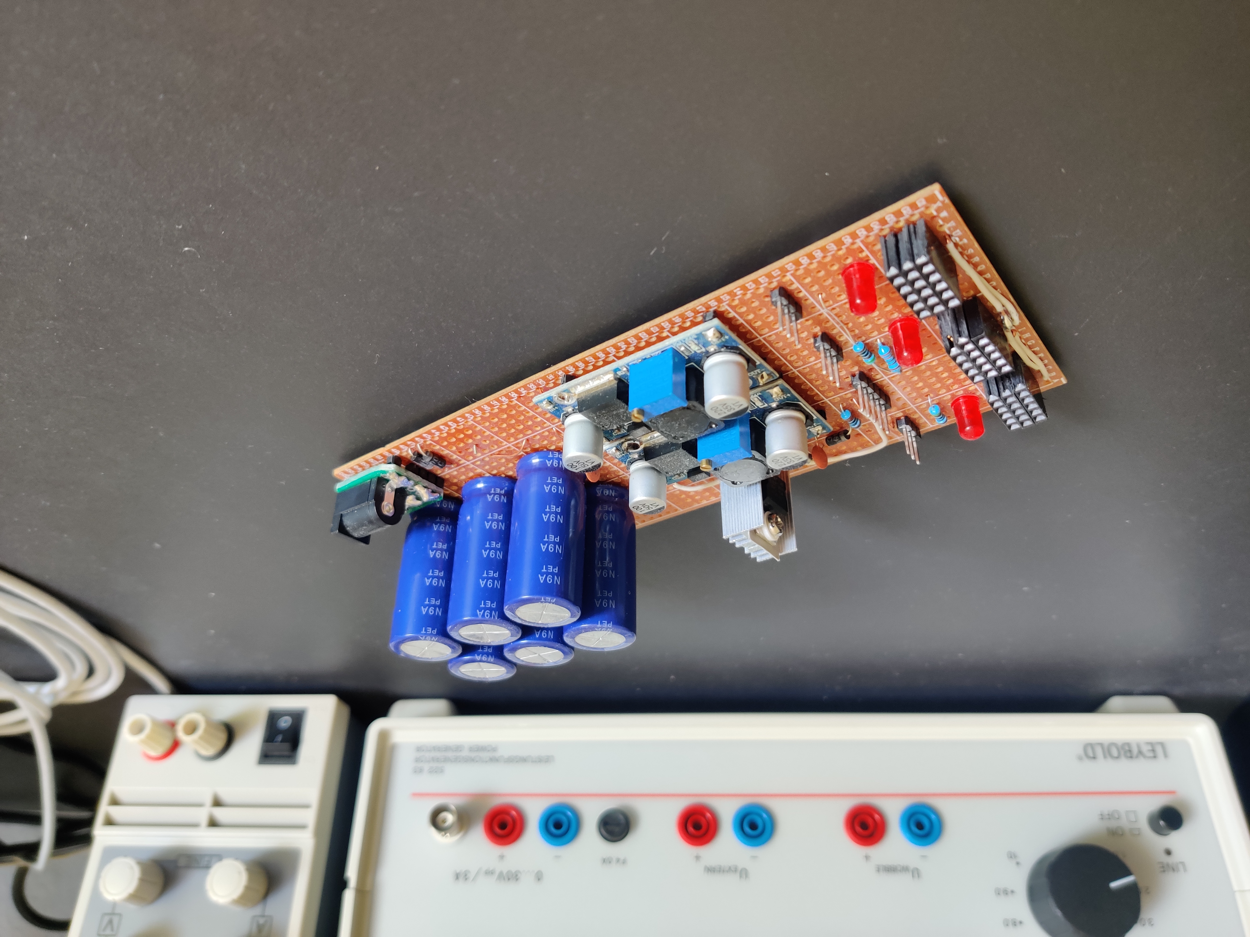
Chapter 2: Build a prototype of a bipolar ±12V power supply

  • used a lot of sources for designing the circuitry, especially the Make: Analog Synthesizers Book from Music from outer space
  • Didn't want to use two 9V block batteries

How does it work?

  1. A 14V AC voltage is fed into this power supply from an exteral transformer (from Roland, bought from Thomann)
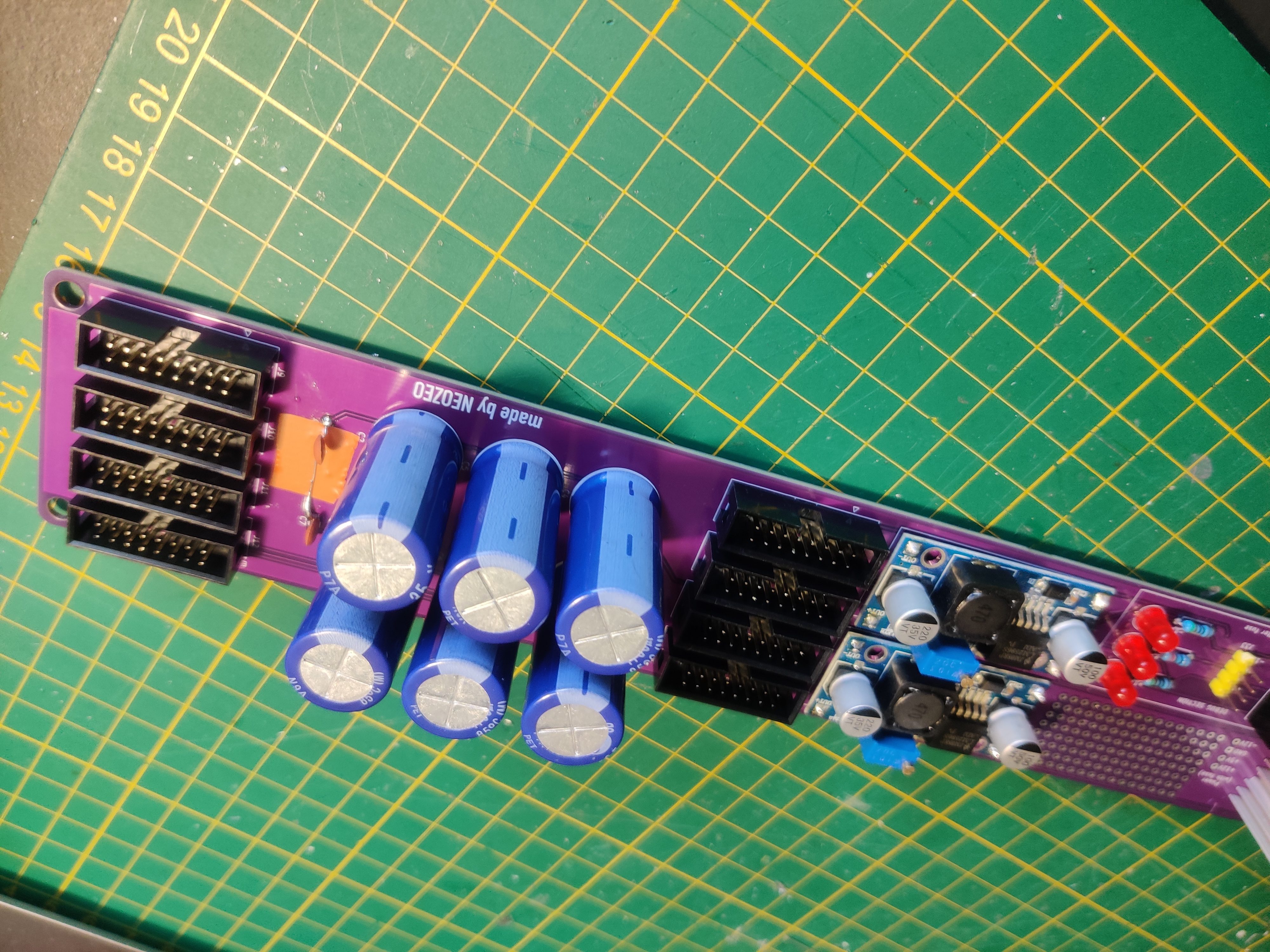
  2. A half bridge rectifier + 6x 4700uF capacitors are used to generate a bipolar, but unstable voltages (If I remember around 20V)
  3. For +12V and +5V, step down converters are used (LM2596S) to avoid linear voltage regulators that heat up
  4. For -12V, the L7912 linear voltage regulator is used, as I did not saw another easy way

Chapter 3: Play with circuits from Look Mum No Computer

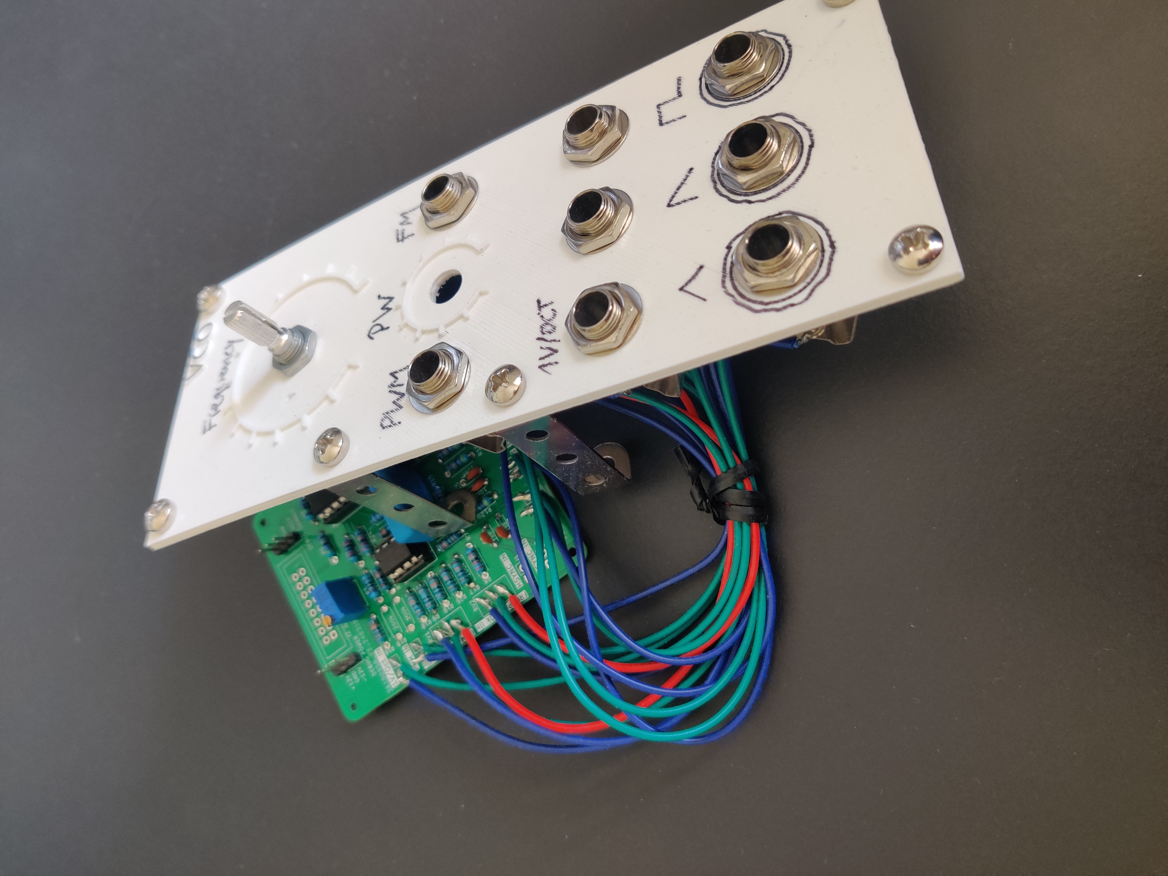
  • Built a simple VCO
  • Built a simple VCF (voltage controlled filter)
  • Made a lot of plans
    • chose Cosmo standard for dimensions and electronic properties of signals etc.
    • could not decide on whether the module height of 16cm or 20cm is better. 16cm seemed more handy, but 20cm are definitely a good decision! You have so much space and the synth takes in the room it deserves!

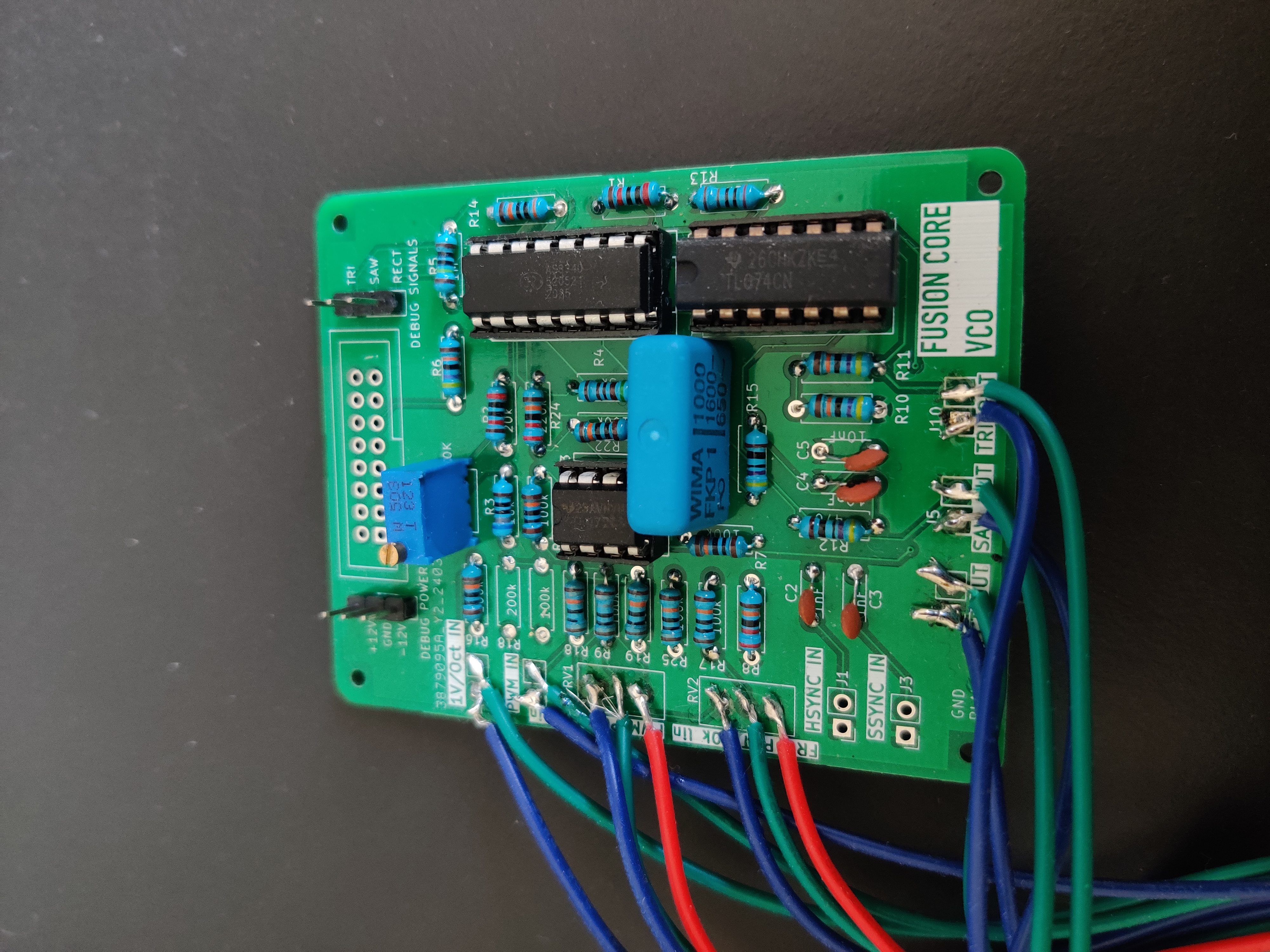
Chapter 4: Design first revision of VCO (and do first PCB designing experience)

  1. Build and validate the circuitry found on the internet
  1. Design first revision & meet with friend to solder it
  • had some faults and wrong footprints, I wasn't happy
  • also, the holes at the corners were a lot too small to mount it anywhere
  1. Design & 3D-print the front panel (with a height of 16cm)

Chapter 5: Meet with friend to build the case

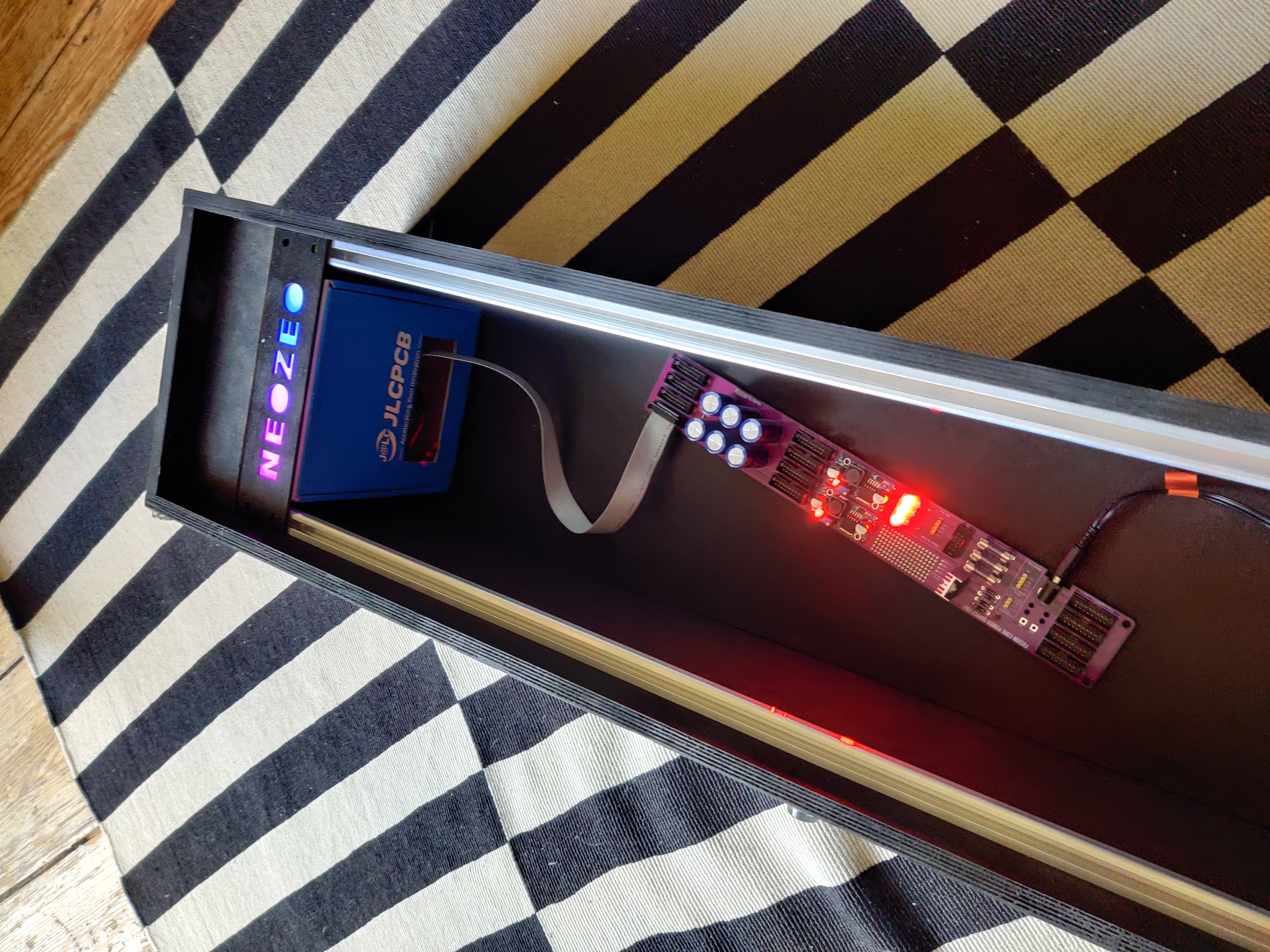
  • Wooden box sprayed black
  • 1m wide from the inside, 20cm deep, 20cm height from the inside
  • materials bought from Bauhaus Germany, for around 55€
  • used 2x Adam Hall 6161 as cheap rails

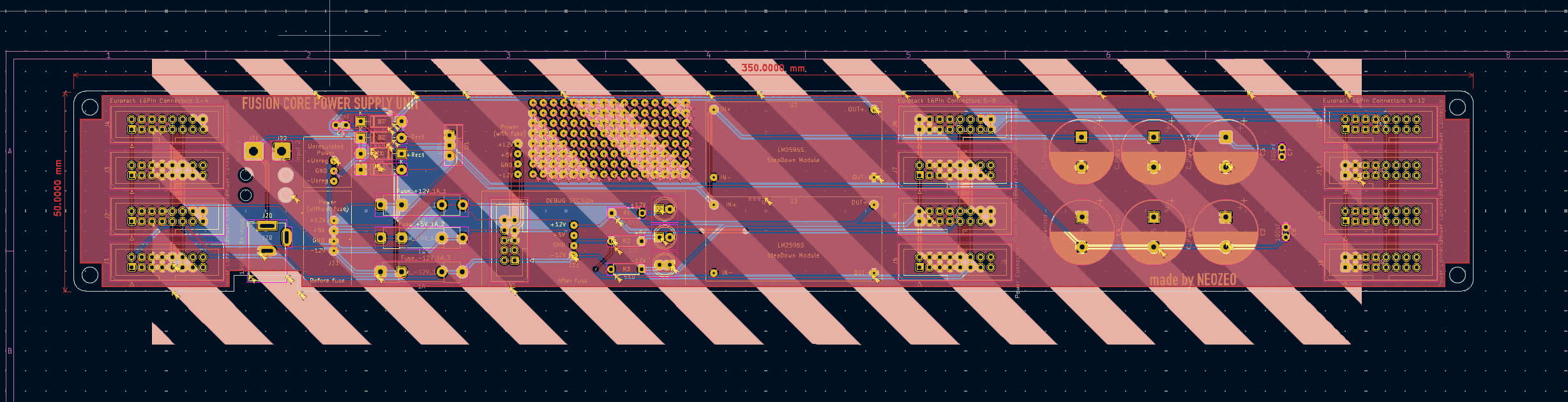
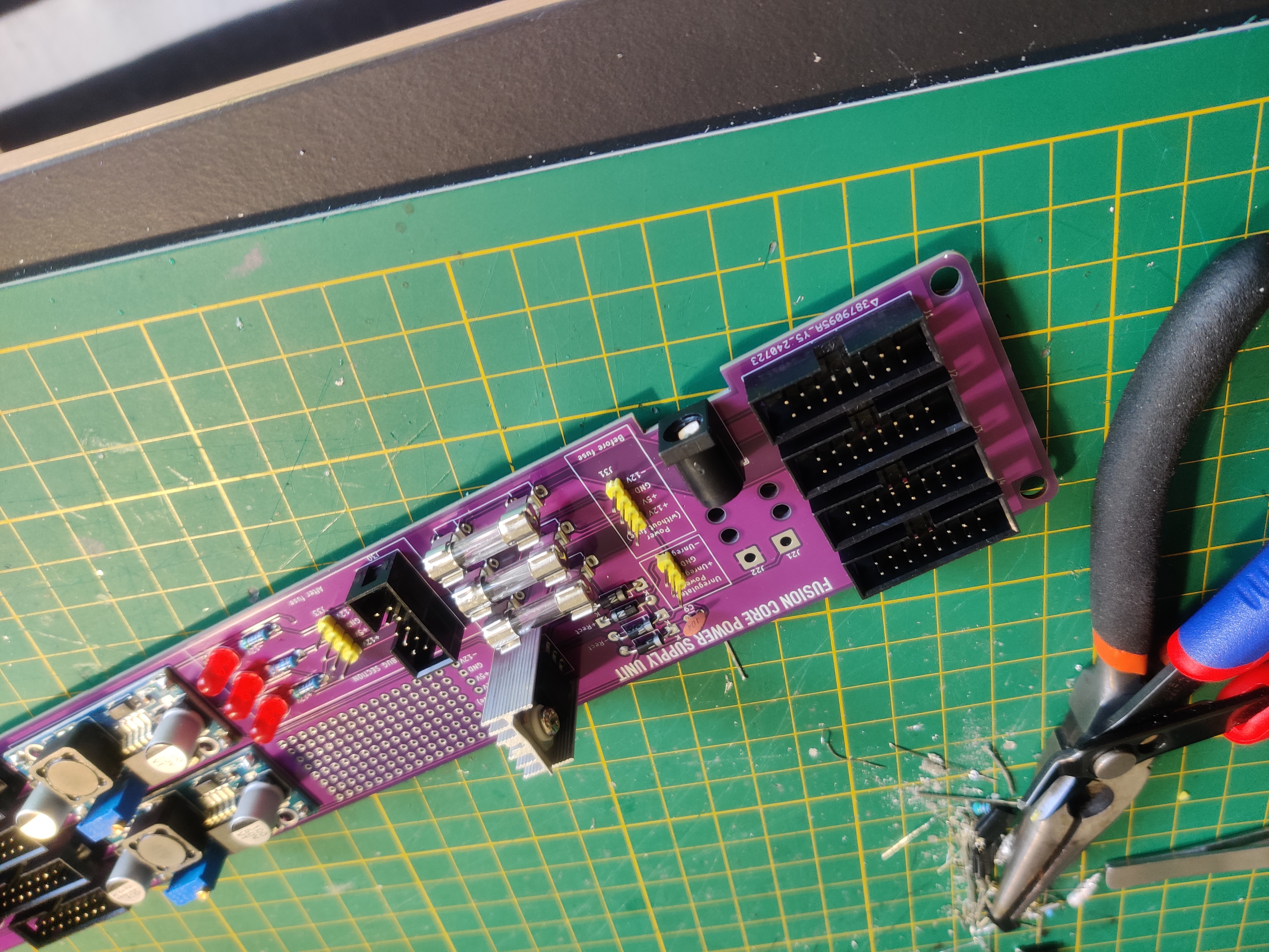
Chapter 6: Design proper PSU without the anxiety of shorts because of bad soldering

  • similar circuitry like the prototype power supply
  • but it has a lot of proper 16pin eurorack connectors
  • and it has fuses, a prototype area and debug headers
  • contains very ugly mistake: The main power PCB traces are a little thin

Next challenges:

  • Make PCB trace width bigger
  • Connect all Gate / CV Eurorack ports

Chapter 7: Build a CLI to search in my part inventory

  • I ordered too many parts and unfortunately cannot remember all the component IDs! TL072 for my OpAmps is easy, but MCP3008 for an 8 channel ADC is not!
  • you find it here: https://github.com/NEOZEO64/InventoryTool
  • basically, it is only a json parser with some array filtering mechanics

Chapter 7: Build decoration module

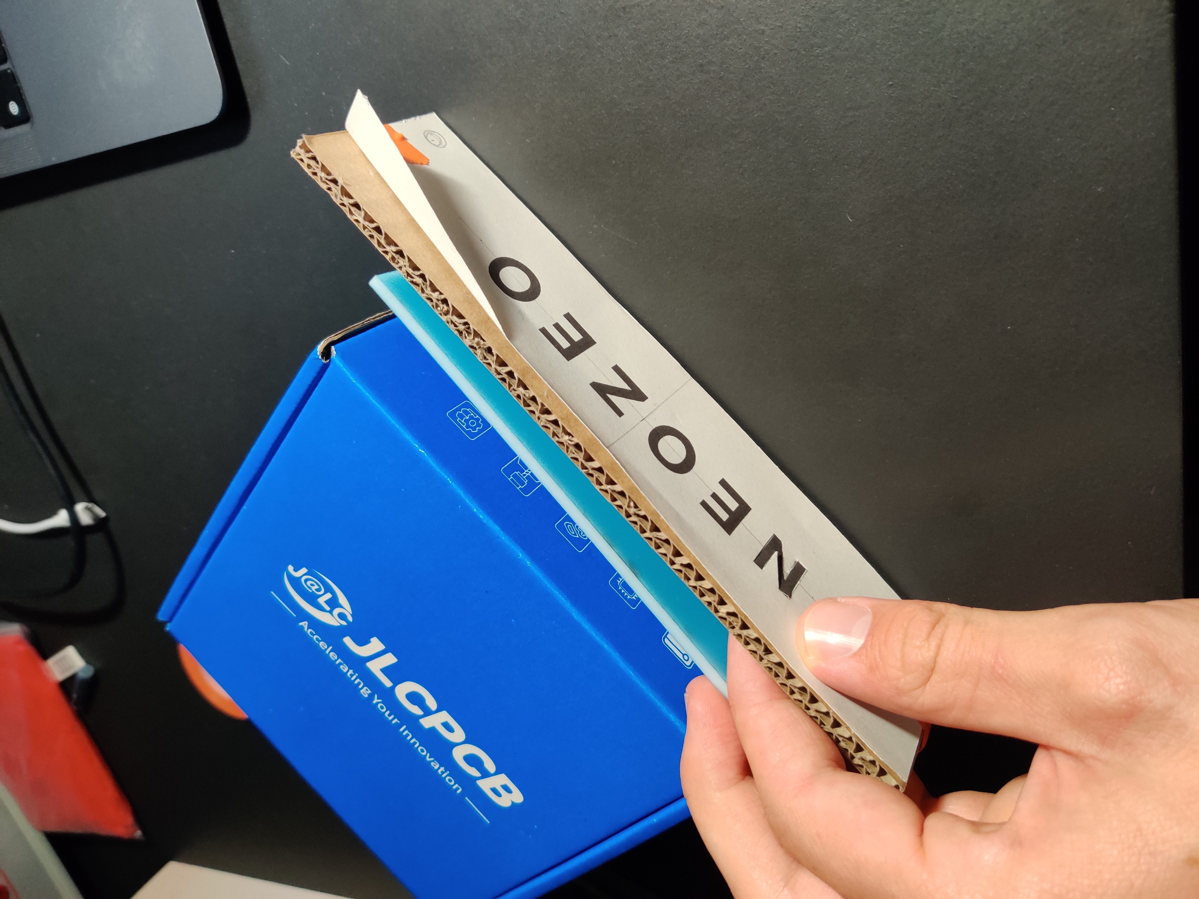
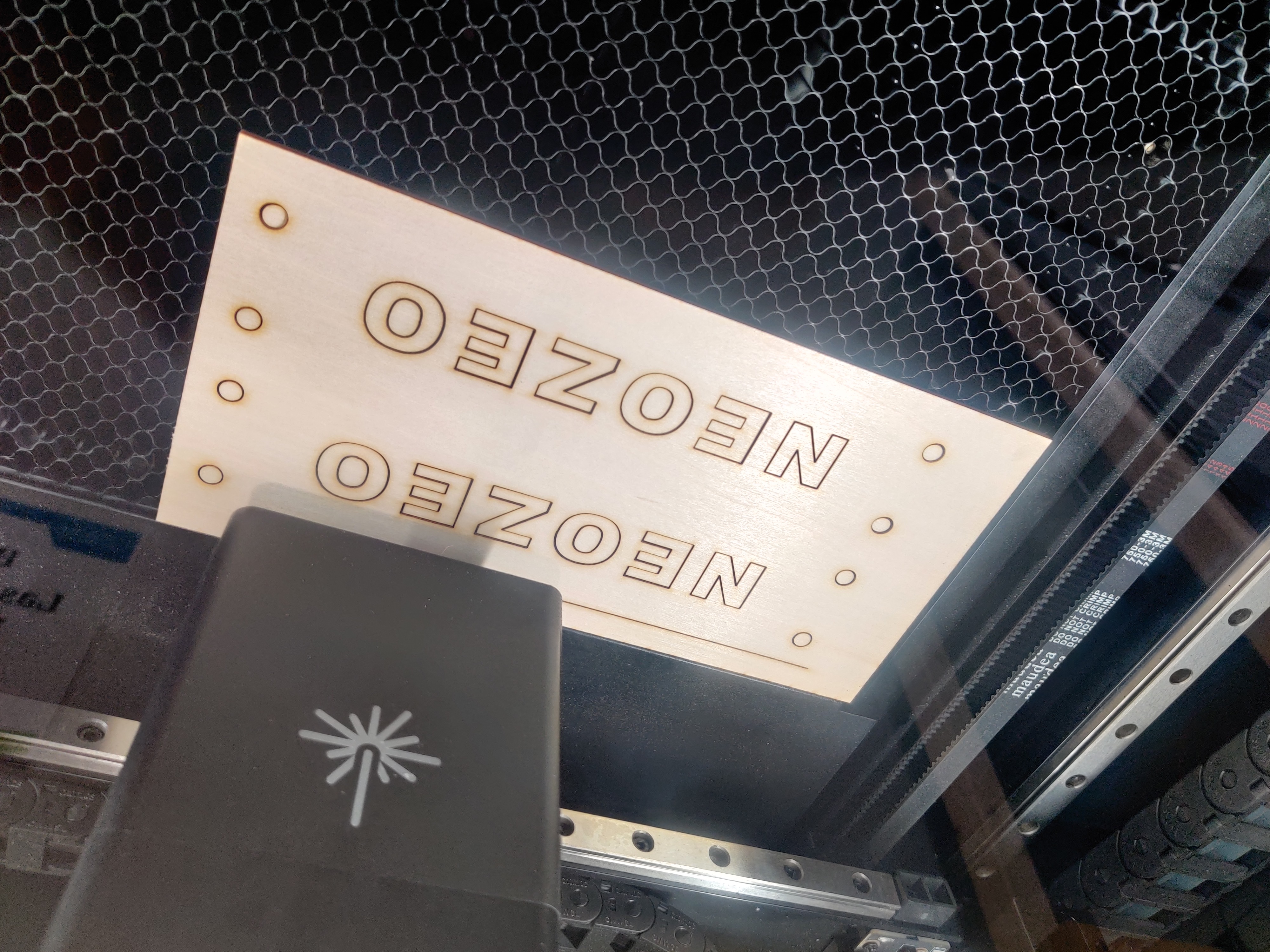
  • It really was necessary to put my nametag on the synth
  • But with RGB leds!
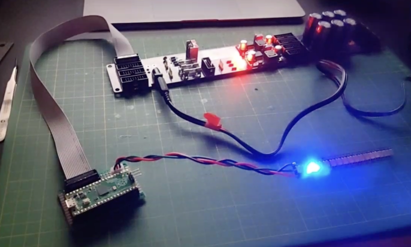
  • Used a Raspberry Pi Pico, powered by the 5V line on the eurorack plug
  • Used WS2812B RGB leds
  • Soldered a simple PCB and wrote a small MicroPython firmware for the Pico to control the LEDs (found at ./NEOZEO module/main.py)

Chapter 8: Hack AAAPPPCCC from Look Mum No Computer into my synth

(easy one-day project)

  • measured dimensions
  • designed some laser cutter guide
  • laser cutted at the student research center
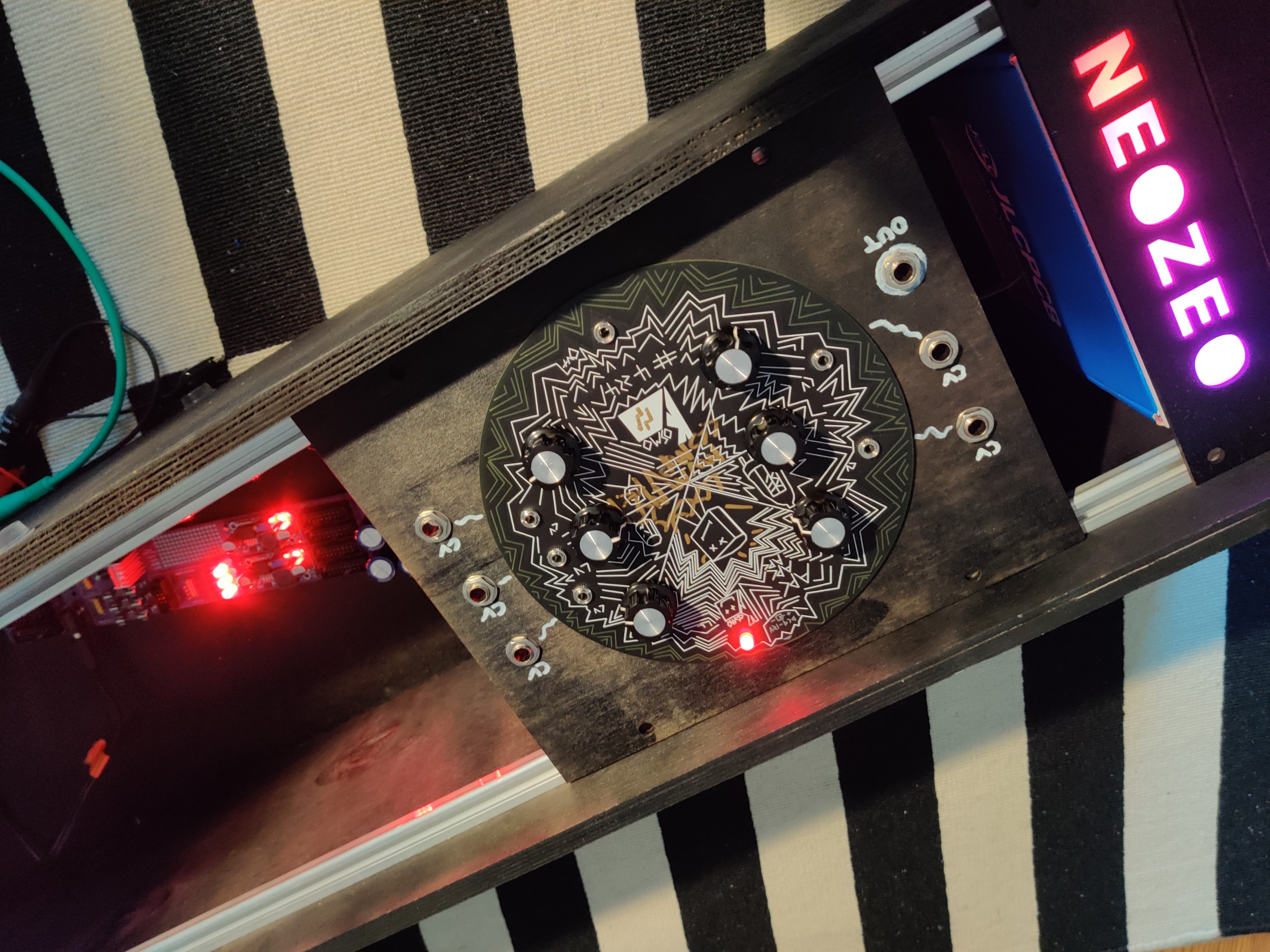
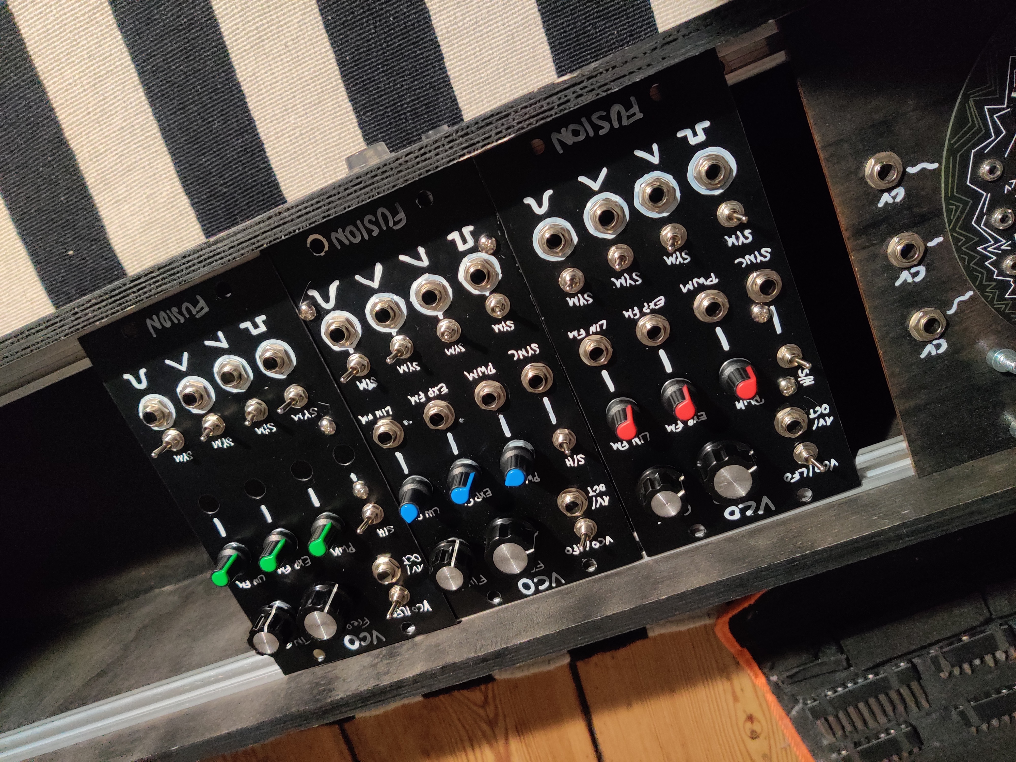
  • sprayed black and drew fancy UI
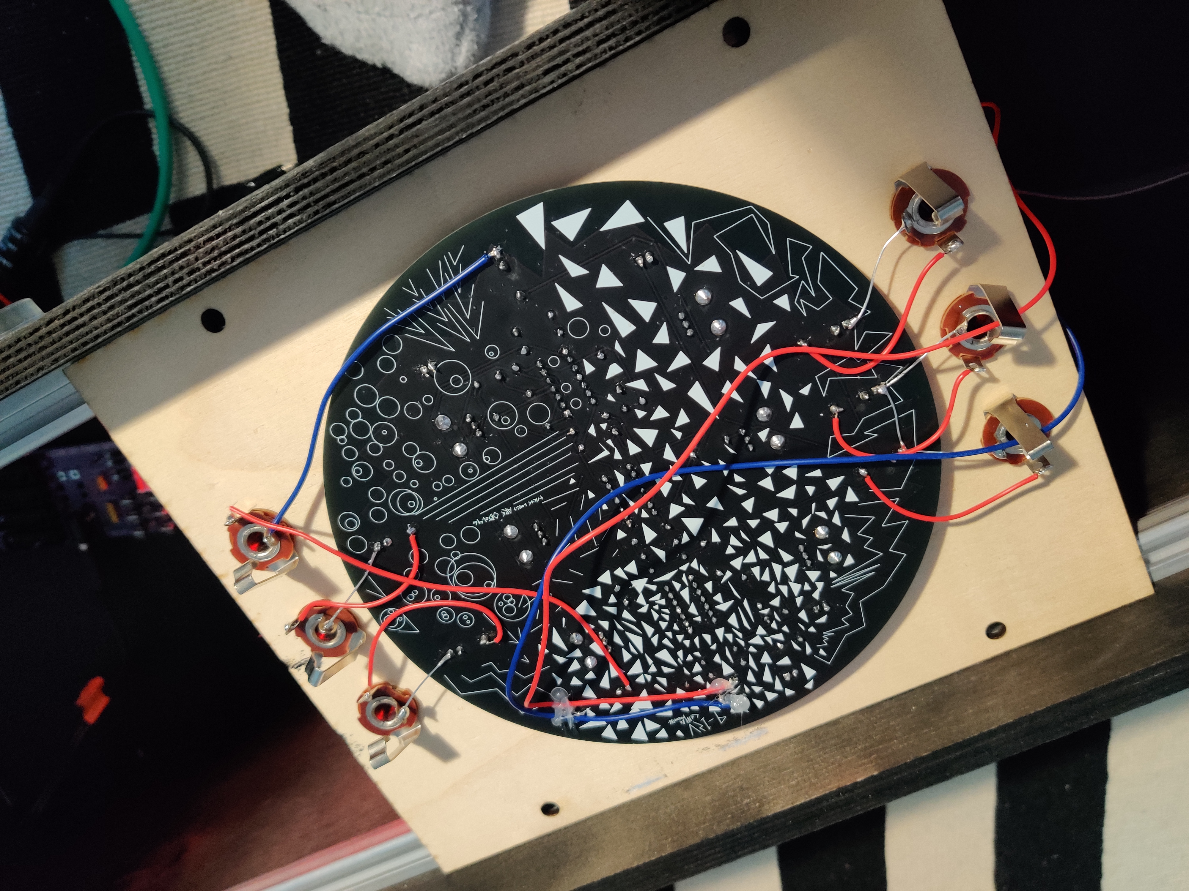
  • soldered on adapter connectors (fortunately the AAAPPPCCC module needs 12VDC for power that can be easily provided from the eurorack plugs, also the audio signal levels are fine)
  • done

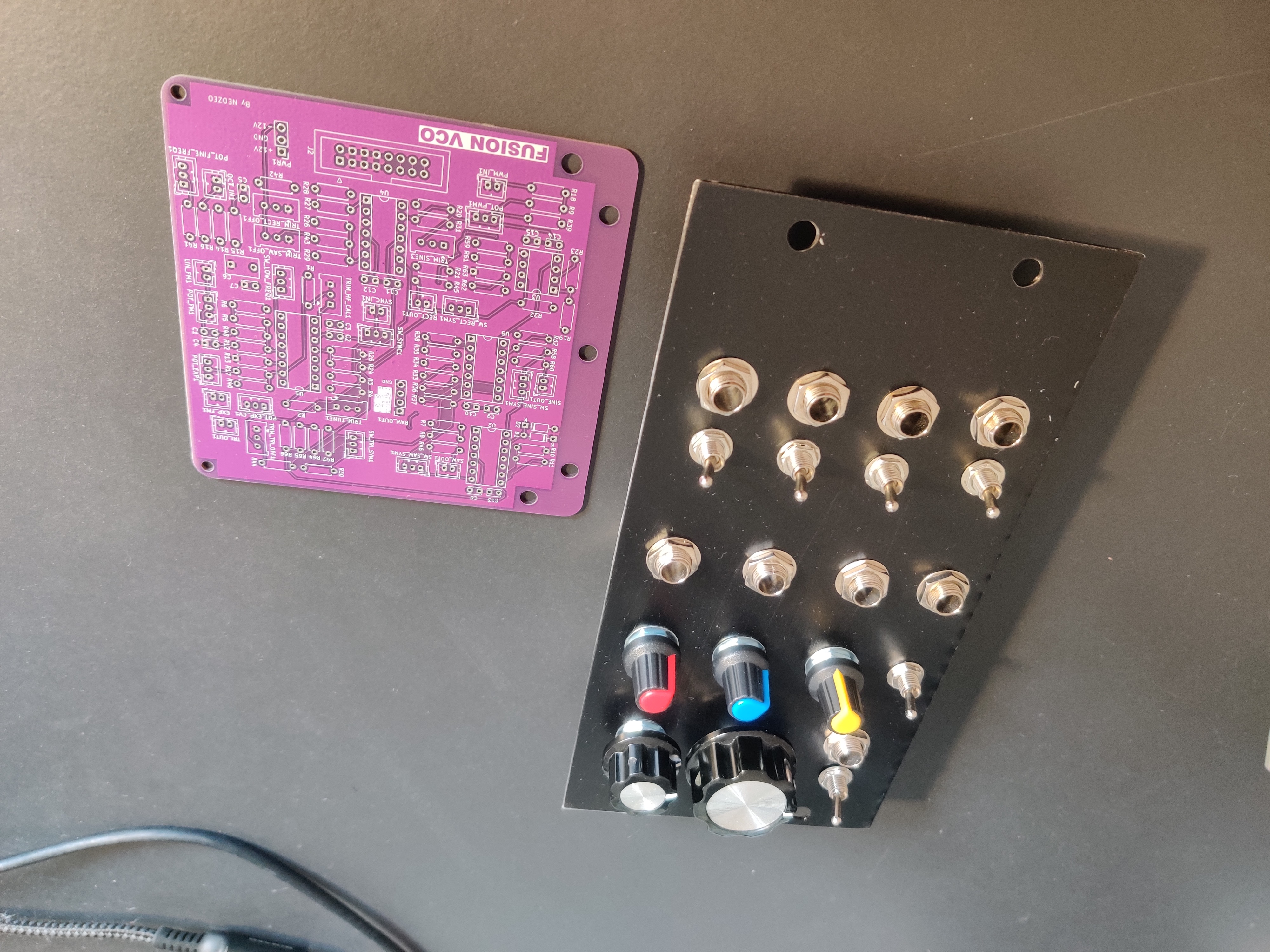
Chapter 9: Design proper working, functional VCO

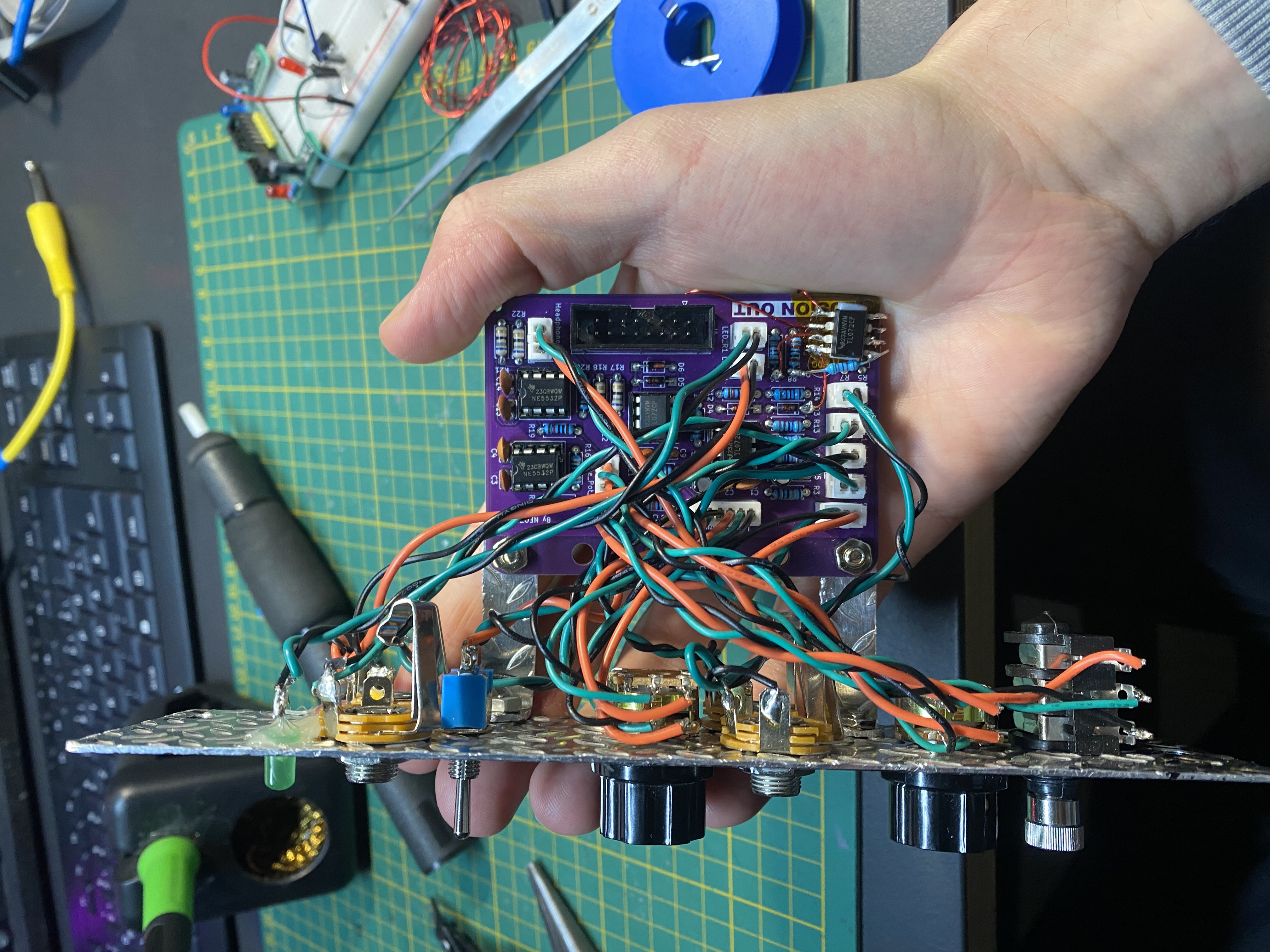
Chapter 10: Design audio output module

  • buffers synth audio signals and attenuates them significantly to line level and use NE5532 opamps for headphone output
  • can switch between mono & stereo!

Chapter 11: Design some util modules

simple mixer (without voltage control of the volume)
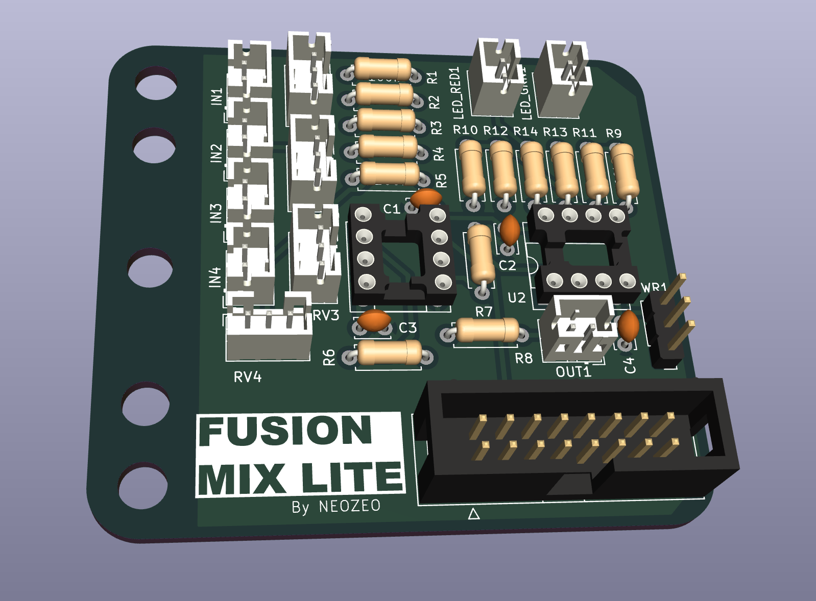
  • 4 sound inputs with potentiometers volume control
  • 1 sound output
  • not yet manufactured & built

simple math module

  • Functions
  • Invert sound
  • remove offset voltage
  • add offset
  • attenuate / amplify (using potentiometer as control)
  • not yet manufactured

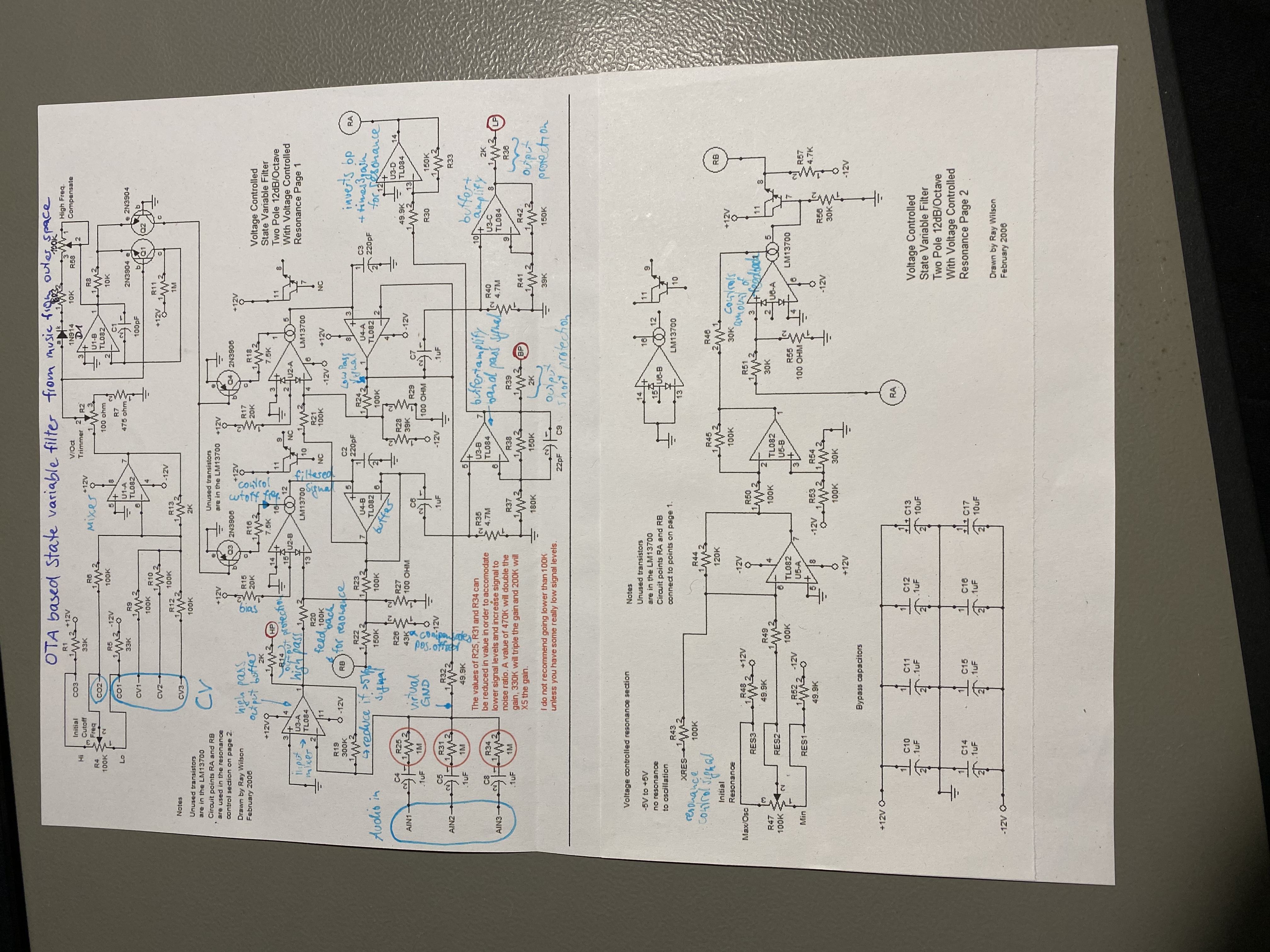
Chapter 4: VCF (state variable)

  • in heavy development
  • First design on breadboard works, based on LM13700 Operational Transconductance Amplifier, but I want to make sure it workes in every situation and the output is in voltage bounds
  • current challenge: Linear to exponential converter
    • if understood, the VCA module is also unlocked for design!
  • automated the SPICE simulation with python to find variation of cutoff frequency due to input voltage changes
  • trying to understand state variable filter from music from outer space:

Future chapters

  • VCA
  • Mixer
  • Teensy 4.1 as digital signal processor for reverb / echo / delay / distortion / flanger / choir effects
  • Splitter
  • Clock & Clock divider (using 74HC Chips)
  • ADSR!
  • Sample & Hold
  • Quantizer & Transposer
  • Noise source & Random signal generator
  • switch multiplex / MUX
  • EQ
  • Random
  • Sample Player
  • Sample Recorder
  • Midi to CV

Parts

40
QtyValueFootprintReferences
12100kResistor_THT:R_Axial_DIN0207_L6.3mm_D2.5mm_P7.62mm_HorizontalR1, R2, R4, R5, R6, R7, R8, R9, R10, R11, R12, R13
51kResistor_THT:R_Axial_DIN0207_L6.3mm_D2.5mm_P7.62mm_HorizontalR14, R15, R16, R17, R18
4100nFCapacitor_THT:C_Disc_D3.4mm_W2.1mm_P2.50mmC2, C3, C4, C5
3100kConnector_JST:JST_PH_B3B-PH-K_1x03_P2.00mm_VerticalRV1, RV2, RV3
11MResistor_THT:R_Axial_DIN0207_L6.3mm_D2.5mm_P7.62mm_HorizontalR3
122uFCapacitor_THT:C_Radial_D6.3mm_H11.0mm_P2.50mmC1
1DC InConnector_JST:JST_PH_B2B-PH-K_1x02_P2.00mm_VerticalDC_IN1
1DC OutConnector_JST:JST_PH_B2B-PH-K_1x02_P2.00mm_VerticalDC_OUT1
1Debug PowerConnector_PinHeader_2.54mm:PinHeader_1x03_P2.54mm_VerticalPWR1
1Inv InConnector_JST:JST_PH_B2B-PH-K_1x02_P2.00mm_VerticalINV_IN1
1Inv OutConnector_JST:JST_PH_B2B-PH-K_1x02_P2.00mm_VerticalINV_OUT1
1Neg Off InConnector_JST:JST_PH_B2B-PH-K_1x02_P2.00mm_VerticalNEG_OFF_IN1
1Neg Off OutConnector_JST:JST_PH_B2B-PH-K_1x02_P2.00mm_VerticalNEG_OFF_OUT1
1Off InConnector_JST:JST_PH_B2B-PH-K_1x02_P2.00mm_VerticalOFF_IN1
1Off OutConnector_JST:JST_PH_B2B-PH-K_1x02_P2.00mm_VerticalOFF_OUT1
1Power ConnectorConnector_IDC:IDC-Header_2x08_P2.54mm_VerticalJ1
1Scale InConnector_JST:JST_PH_B2B-PH-K_1x02_P2.00mm_VerticalSCALE_IN1
1Scale outConnector_JST:JST_PH_B2B-PH-K_1x02_P2.00mm_VerticalSCALE_OUT1
1TL072Package_DIP:DIP-8_W7.62mm_SocketU1
1TL074Package_DIP:DIP-14_W7.62mm_SocketU2

More from carl-becker/fusion-core

5
  • 2 layers350 × 50 mmPSU, the printed circuit board in 3D

    PSU

    carl-becker/fusion-core

    DIY analog modular synth

    174 parts
  • 2 layers100 × 100 mmVCO, the printed circuit board in 3D

    VCO

    carl-becker/fusion-core

    DIY analog modular synth

    108 parts
  • 2 layers80 × 57.5 mmAudio Output, the printed circuit board in 3D

    Audio Output

    carl-becker/fusion-core

    DIY analog modular synth

    57 parts
  • 2 layers60 × 55 mmMix Lite Module, the printed circuit board in 3D

    Mix Lite Module

    carl-becker/fusion-core

    DIY analog modular synth

    33 parts

Similar boards

  • 2 layers148 × 84.5 mmPanel daisy, the printed circuit board in 3D

    Panel daisy

    ohmtech-rdi/eurorack-blocks

    Software to Hardware Prototyping for Eurorack using C++, Max/Gen~ or Faust

    259 parts410
  • 2 layers39.6 × 99.1 mmESP32-Eurorack Audio, the printed circuit board in 3D

    ESP32-Eurorack Audio

    ctag-fh-kiel/ctag-tbd

    CTAG TBD >>to be determined<< an extendible open source Eurorack sound module

    128 parts260
  • 4 layers121.9 × 109.2 mmPlinkyblack hwmidi jacks, the printed circuit board in 3D

    Plinkyblack hwmidi jacks

    plinkysynth/plinky_public

    a public release of the plinky sw and hw

    300 parts227
  • 2 layers58 × 110 mmVco core, the printed circuit board in 3D

    Vco core

    shmoergh/moduleur

    Fully analog DIY-friendly modular synth

    146 parts222
  • 2 layers37 × 113.9 mmVCO, the printed circuit board in 3D

    VCO

    nickajeglin/Eurorack-pcbs

    A collection of easy to solder DIY eurorack PCB's

    104 parts208
  • 2 layers111.3 × 106.4 mmSuper Sixteen v1, the printed circuit board in 3D

    Super Sixteen v1

    matthewcieplak/super-sixteen

    Code and schematics for the Super Sixteen Eurorack sequencer

    141 parts171
  • 2 layers85.1 × 62.2 mmMic extension board, the printed circuit board in 3D

    Mic extension board

    StoneRose35/cortexguitarfx

    guitar effects processor implemented on various arm cortex platforms

    75 parts146

Questions

How big is the Math Module PCB?

It measures 60 × 60 mm and has 2 copper layers, 1.6 mm thick.

What parts does the Math Module use?

40 parts, built around the TL072. The full list of its parts is on this page, with links to each part's symbol and footprint where PCBKit's library has them.

Where can I download the Math Module KiCad files?

From the carl-becker/fusion-core repository on GitHub, at the commit this page was made from: the board is Math/Math-Module/Math-Module.kicad_pcb. PCBKit opens the board in the browser, with nothing to install.

Can I use the Math Module design in my own project?

Its repository states no licence, so its author keeps all rights: ask carl-becker before reusing the design.