2 layers110 × 31.5 mm
 CapnKernel/led-tester
A circuit to characterise the behaviour of LEDs.
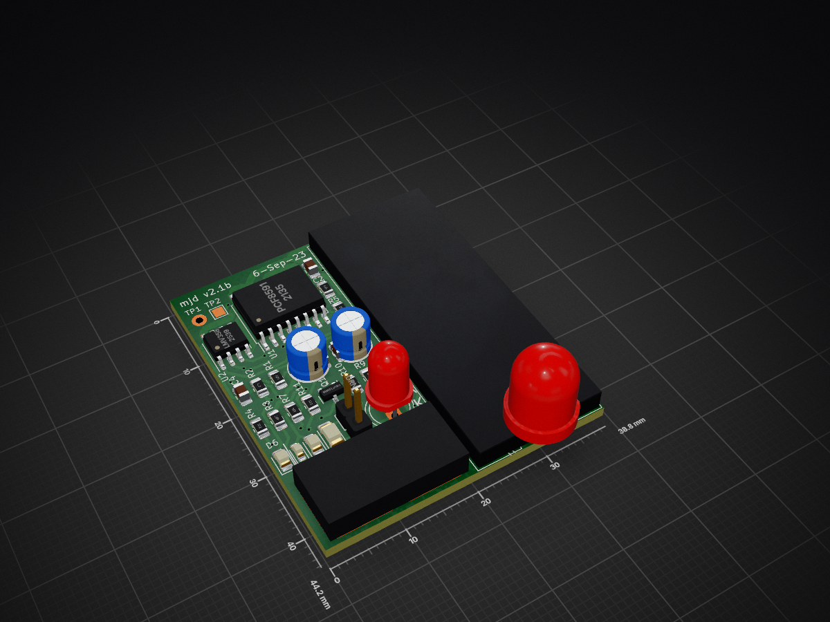
Led tester is an open-source printed circuit board by CapnKernel, from the CapnKernel/led-tester repository on GitHub, published under the MIT licence. It is a 2-layer board of 38.8 × 44.2 mm with 37 parts on 42 nets, routed with 356 tracks and 101 vias.
It is built around the LMV358, PCF8591T/2 and MMBT3904. Its parts include 14 resistors, 7 diodes, 6 capacitors, 2 ICs and 1 transistor.


A circuit to characterise the behaviour of LEDs.
| Qty | Value | Footprint | References |
|---|---|---|---|
| 4 | 470R | Resistor_SMD:R_0805_2012Metric_Pad1.20x1.40mm_HandSolder | R1, R2, R3, R10 |
| 3 | R | Resistor_SMD:R_0603_1608Metric | R12, R13, R14 |
| 2 | 100n | Capacitor_SMD:C_0805_2012Metric_Pad1.18x1.45mm_HandSolder | C2, C4 |
| 2 | 10k | Resistor_SMD:R_0805_2012Metric_Pad1.20x1.40mm_HandSolder | R5, R6 |
| 2 | 10u | Capacitor_THT:CP_Radial_D5.0mm_P2.00mm | C1, C3 |
| 2 | 10u | Capacitor_SMD:C_0805_2012Metric_Pad1.18x1.45mm_HandSolder | C5, C6 |
| 2 | 1k | Resistor_SMD:R_0805_2012Metric_Pad1.20x1.40mm_HandSolder | R4, R11 |
| 2 | GRN | LED_SMD:LED_0805_2012Metric_Pad1.15x1.40mm_HandSolder | D2, D6 |
| 1 | 100R | Resistor_SMD:R_0805_2012Metric_Pad1.20x1.40mm_HandSolder | R7 |
| 1 | 2k7 | Resistor_SMD:R_0805_2012Metric_Pad1.20x1.40mm_HandSolder | R9 |
| 1 | 4R7 | Resistor_SMD:R_0805_2012Metric_Pad1.20x1.40mm_HandSolder | R8 |
| 1 | Arduino_Mini | aalib:Arduino Mini | M1 |
| 1 | GRN | LED_SMD:LED_1206_3216Metric_Pad1.42x1.75mm_HandSolder | D3 |
| 1 | GRN | LED_SMD:LED_0603_1608Metric_Pad1.05x0.95mm_HandSolder | D1 |
| 1 | GRN | Connector_PinHeader_2.54mm:PinHeader_1x02_P2.54mm_Vertical | D4 |
| 1 | GRN | aalib:LED_D5.0mm | D5 |
| 1 | LED_RAGB | aalib:LED_D8.0mm-4_RGB | D7 |
| 1 | LMV358 | Package_SO:SOIC-8_3.9x4.9mm_P1.27mm | U2 |
| 1 | MMBT3904 | Package_TO_SOT_SMD:SOT-23 | Q1 |
| 1 | MountingHole | aalib:AlignmentSlot | H1 |
| 1 | PCF8591 | Package_SO:SOIC-16W_7.5x10.3mm_P1.27mm | U1 |
| 1 | SolderJumper_2_Bridged | Jumper:SolderJumper-2_P1.3mm_Bridged_Pad1.0x1.5mm | JP2 |
| 1 | SolderJumper_2_Open | aalib:TestPad | JP1 |
| 1 | SolderJumper_2_Open | Jumper:SolderJumper-2_P1.3mm_Open_Pad1.0x1.5mm | JP3 |
| 1 | TestPoint | TestPoint:TestPoint_THTPad_D2.0mm_Drill1.0mm | TP1 |
| 1 | TestPoint | TestPoint:TestPoint_Pad_1.5x1.5mm | TP2 |
It measures 38.8 × 44.2 mm and has 2 copper layers, 1.6 mm thick.
37 parts, built around the LMV358, PCF8591T/2 and MMBT3904. The full list of its parts is on this page, with links to each part's symbol and footprint where PCBKit's library has them.
From the CapnKernel/led-tester repository on GitHub, at the commit this page was made from: the board is led-tester.kicad_pcb and its schematic led-tester.kicad_sch. PCBKit opens the board in the browser, with nothing to install.
Its repository publishes it under the MIT licence: you may reuse it on that licence's terms (keep the author's notice, and for a copyleft licence share your changes alike).


janithcbk123/Automated-Greenhouse
Greenhouse Automation Project


conradbuck/magical-toys-work
Designing Integration PCBs to connect breadboard components to simplify assembly of prototypes.


