4 layers90 × 90 mm
KICAD reflow oven
leodk27/Reflow-oven-Custom
Reflow oven project based on custom PCB and programming
125 partsMIT

 canardos/bake-n-flow
Hardware and firmware files for an STM32 based toaster reflow oven
Reflow toaster mainboard is an open-source printed circuit board by canardos, from the canardos/bake-n-flow repository on GitHub, published under the MIT licence. It is a 2-layer board of 49.8 × 54.9 mm with 46 parts on 106 nets, routed with 455 tracks and 66 vias.
It is built around the MAX31856, TLV75533PDBV and SI1308EDL. Its parts include 19 capacitors, 7 connectors, 6 resistors, 4 ICs and 2 transistors. It belongs with the computers and single-board computers boards and the STM32 boards of this library.


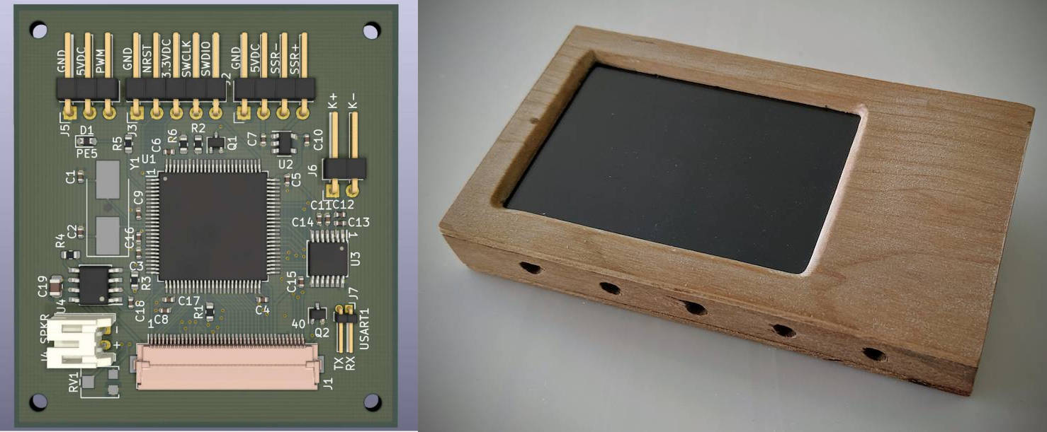
[!Warning] This is personal project. It was built and works without issue for my purposes. It is made public here in case some part of it is useful to others, but neither the hardware nor firmware have been rigorously tested.
Features:
This repo contains the firmware and PCB design.
See custom electronics projects at DuckToast.com for full project details.
https://github.com/canardos/bake-n-flow/assets/14832310/401d4c1e-f360-4829-90d8-4b5ea61bf341
The project uses the PlatformIO dependency management/build system. If you have PlatformIO installed, executing the run command in the root folder should 🙏 be all that is required for a successful build. The platformio.ini file contains the required configuration and PlatformIO will download the required dependencies and toolchain.
1. Clone repo and download submodules
> git clone https://github.com/canardos/bake-n-flow.git
> cd bake-n-flow
> git submodule update --init
2. Build firmware (PlatformIO must be installed)
> pio run

Processing release (platform: ststm32; board: genericSTM32F103VD; framework: cmsis)
-----------------------------------------------------------------------------------
Verbose mode can be enabled via `-v, --verbose` option
CONFIGURATION: https://docs.platformio.org/page/boards/ststm32/genericSTM32F103VD.html
PLATFORM: ST STM32 (19.7.0) > STM32F103VD (64k RAM. 384k Flash)
HARDWARE: STM32F103VDT6 72MHz, 64KB RAM, 384KB Flash
DEBUG: Current (stlink) External (blackmagic, cmsis-dap, jlink, stlink)
PACKAGES:
 - framework-cmsis @ 2.50501.200527 (5.5.1)
 - framework-cmsis-stm32f1 @ 4.3.5
 - tool-ldscripts-ststm32 @ 0.2.0
 - toolchain-gccarmnoneeabi @ 1.120301.0 (12.3.1)
LDF: Library Dependency Finder -> https://bit.ly/configure-pio-ldf
LDF Modes: Finder ~ chain, Compatibility ~ soft
Found 4 compatible libraries
Scanning dependencies...
Dependency Graph
|-- libpekin @ 0.2.1
|-- libpekin_stm32
Building in release mode
Compiling piobuild/build/release/FrameworkCMSIS/gcc/startup_stm32f103xe.o
...3. Upload to device
Similarly, use pio run --target upload to upload the firmware to the device. You'll likely need to update the upload settings in platformio.ini to reflect your settings, or use your own upload tool.
> pio run --target upload

Configuring upload protocol...
AVAILABLE: blackmagic, dfu, jlink, serial, stlink
CURRENT: upload_protocol = stlink
Uploading piobuild/build/release/firmware.elf
xPack OpenOCD, x86_64 Open On-Chip Debugger 0.10.0+dev-00378-ge5be992df (2020-06-26-09:27)
Licensed under GNU GPL v2
For bug reports, read
        http://openocd.org/doc/doxygen/bugs.html
debug_level: 1

hla_swd
target halted due to debug-request, current mode: Thread
xPSR: 0x01000000 pc: 0x0800108c msp: 0x20010000
** Programming Started **
** Programming Finished **
** Verify Started **
** Verified OK **
** Resetting Target **
shutdown command invoked
======================== [SUCCESS] Took 12.58 seconds =================================
4. [optional] Create project files for IDE
If you want to view/edit the project in your favorite IDE, use PlatformIO to generate the appropriate setup/workspace files and then import the project in the IDE:
> pio project init --ide [atom|clion|codeblocks|eclipse|emacs|netbeans|qtcreator|sublimetext|vim|visualstudio|vscode]See the PlatformIO documentation for further details.
Platform dependencies
If you wish to use a different build system, you will need:
| ST STM32 CMSIS headers | Peripheral/register definitions |
| CMSIS headers/source | CMSIS HAL functionality - SysTick_Config, NVIC_xxx etc. |
| CMSIS Cortex-M3 system source | SystemInit()/SystemCoreClockUpdate() implementation and SystemCoreClock |
| Startup source file | ASM file containing the startup code and vector table |
| Linker script | Tells the linker how to setup everything in flash/SRAM |
All of these are available in the STM32 SDK available from ST Micro.
Compiling / linking
platformio.ini lists the required compiler flags. Be sure to use --specs=nano.specs and --specs=nosys.specs when linking using your own tools, as the standard lib is be too large and is not used.
The project was compiled and tested with gcc-arm-none-eabi 9.2.1gcc-arm-none-eabi 12.3.1. It should work with any later GCC version and possibly with other compilers. The code contains some GCC flags and some C99 VLAs.
| MCU | STM32F103 with FSMC |
| Flash | >195kb |
| SRAM | >61kb |
It may be possible to get by with less SRAM by using a smaller drawing buffer (currently 40 lines - 38.4 kb)
CMSIS
PlatformIO should automatically include/link the correct headers/sources from the STM32 SDK.
LVGL
LVGL v5.3 (git commit 9f216a55be65ec05c477ac55f73a6efad50f7680) is used. It is included as a Git submodule in thesrc/lvgl folder.
Libpekin
Libpekin is a collection of shared MCU-related code resulting from this and other projects. It's included as a Git submodule in the lib folder. PlatformIO will include the lib subfolders automatically.
The PCB was designed with KiCad v.5, but the files have been upgraded to v.7 and are located in /hardware/pcb. Gerber output for the first and only revision is located in /hardware/pcb/plots.
The design contains minor errors that should be fixed if it is (re)produced. See the blog post here for details.
BakeNFlow
|
+--hardware          | KiCad schematic and board design files
|
+--lib
|  |
|  +--libpekin       | Libpekin platform independent code
|  +--libpekin_stm32 | Libpekin STM32 specific code
|
+--src
|  |
|  +--audio_samples  | Audio sample data
|  +--devices        | Hardware device drivers
|  +--lvgl           | LVGL project
|  +--lvgl_driver    | Display/touch driver for LVGL
|  +--oven           | Oven hardware interface and state management
|  +--reflow         | Reflow data structures and state management
|  +--hal            | (exception handlers etc.)
|  +--ui             | UI code for LVGL
|
|--test | No tests in useThis software is available under the MIT license.
| Qty | Value | Footprint | References |
|---|---|---|---|
| 9 | 0.1uF | Capacitor_SMD:C_0402_1005Metric | C4, C5, C8, C9, C14, C15, C16, C17, C18 |
| 4 | MountingHole_2.2mm_M2 | MountingHole:MountingHole_2.2mm_M2 | , , , |
| 3 | 0.01uF | Capacitor_SMD:C_0402_1005Metric | C3, C11, C13 |
| 2 | 100R | Resistor_SMD:R_0603_1608Metric | R1, R2 |
| 2 | 1uF | Capacitor_SMD:C_0402_1005Metric | C7, C10 |
| 2 | 20k | Resistor_SMD:R_0603_1608Metric | R4, R6 |
| 2 | 24pF | Capacitor_SMD:C_0402_1005Metric | C1, C2 |
| 2 | Si1308EDL | Package_TO_SOT_SMD:SOT-323_SC-70 | Q1, Q2 |
| 1 | 0.47uF | Capacitor_SMD:C_0402_1005Metric | C6 |
| 1 | 10uF | Capacitor_SMD:C_0805_2012Metric | C19 |
| 1 | 20k | trimmer_panasonic:Trimmer_Potentiometer_Panasonic_EVM3W | RV1 |
| 1 | 27k | Resistor_SMD:R_0603_1608Metric | R3 |
| 1 | 330 | Resistor_SMD:R_0603_1608Metric | R5 |
| 1 | 8MHz | Crystal:Crystal_SMD_7050-2Pin_7.0x5.0mm_HandSoldering | Y1 |
| 1 | C | Capacitor_SMD:C_0402_1005Metric | C12 |
| 1 | Door servo | Connector_PinHeader_2.54mm:PinHeader_1x03_P2.54mm_Horizontal | J5 |
| 1 | Ext. | Connector_PinHeader_2.54mm:PinHeader_1x04_P2.54mm_Horizontal | J2 |
| 1 | JTAG | Connector_PinHeader_2.54mm:PinHeader_1x05_P2.54mm_Horizontal | J3 |
| 1 | LED(PE5) | Diode_SMD:D_0603_1608Metric | D1 |
| 1 | LOGO | reflow-toaster-mainboard:duk-20mm | G*** |
| 1 | MAX31856 | Package_SO:TSSOP-14_4.4x5mm_P0.65mm | U3 |
| 1 | NCS2211DR2G | Package_SO:SOIC-8_3.9x4.9mm_P1.27mm | U4 |
| 1 | STM32F103VDTx | Package_QFP:LQFP-100_14x14mm_P0.5mm | U1 |
| 1 | Serial | Connector_PinHeader_1.27mm:PinHeader_1x02_P1.27mm_Horizontal | J7 |
| 1 | Speaker | Connector_JST:JST_PH_S2B-PH-K_1x02_P2.00mm_Horizontal | J4 |
| 1 | TLV75533PDBV | Package_TO_SOT_SMD:SOT-23-5 | U2 |
| 1 | Thermocouple | Connector_PinHeader_2.54mm:PinHeader_1x02_P2.54mm_Horizontal | J6 |
| 1 | ili9481_tft_lcd | Connector_FFC-FPC:Hirose_FH12-40S-0.5SH_1x40-1MP_P0.50mm_Horizontal | J1 |
It measures 49.8 × 54.9 mm and has 2 copper layers, 1.6 mm thick.
46 parts, built around the MAX31856, TLV75533PDBV and SI1308EDL. The full list of its parts is on this page, with links to each part's symbol and footprint where PCBKit's library has them.
From the canardos/bake-n-flow repository on GitHub, at the commit this page was made from: the board is hardware/reflow-toaster-mainboard/reflow-toaster-mainboard.kicad_pcb and its schematic hardware/reflow-toaster-mainboard/reflow-toaster-mainboard.kicad_sch. PCBKit opens the board in the browser, with nothing to install.
Its repository publishes it under the MIT licence: you may reuse it on that licence's terms (keep the author's notice, and for a copyleft licence share your changes alike).
leodk27/Reflow-oven-Custom
Reflow oven project based on custom PCB and programming


IITB-Rocket-Team-Avionics/Ember
Experimental Flight Computer with potential mitigations of previous issues faced by FLYTE and a testbed for new systems.
