4 layers188 × 128.3 mm

 call286/AmigaSID14
Board Render Front | Board Render Back :-------------------------:|:-------------------------: |
AmigaSID is an open-source printed circuit board by call286, from the call286/AmigaSID repository on GitHub. It is a 2-layer board of 130 × 67.5 mm with 49 parts on 122 nets, routed with 512 tracks and 72 vias.
It is built around the 74HC245D, 74HC688D and 74LS00SC, with the BC547 among its other parts. Its parts include 13 capacitors, 6 resistors, 6 connectors, 5 ICs and 1 transistor.


| Board Render Front | Board Render Back |
|---|---|
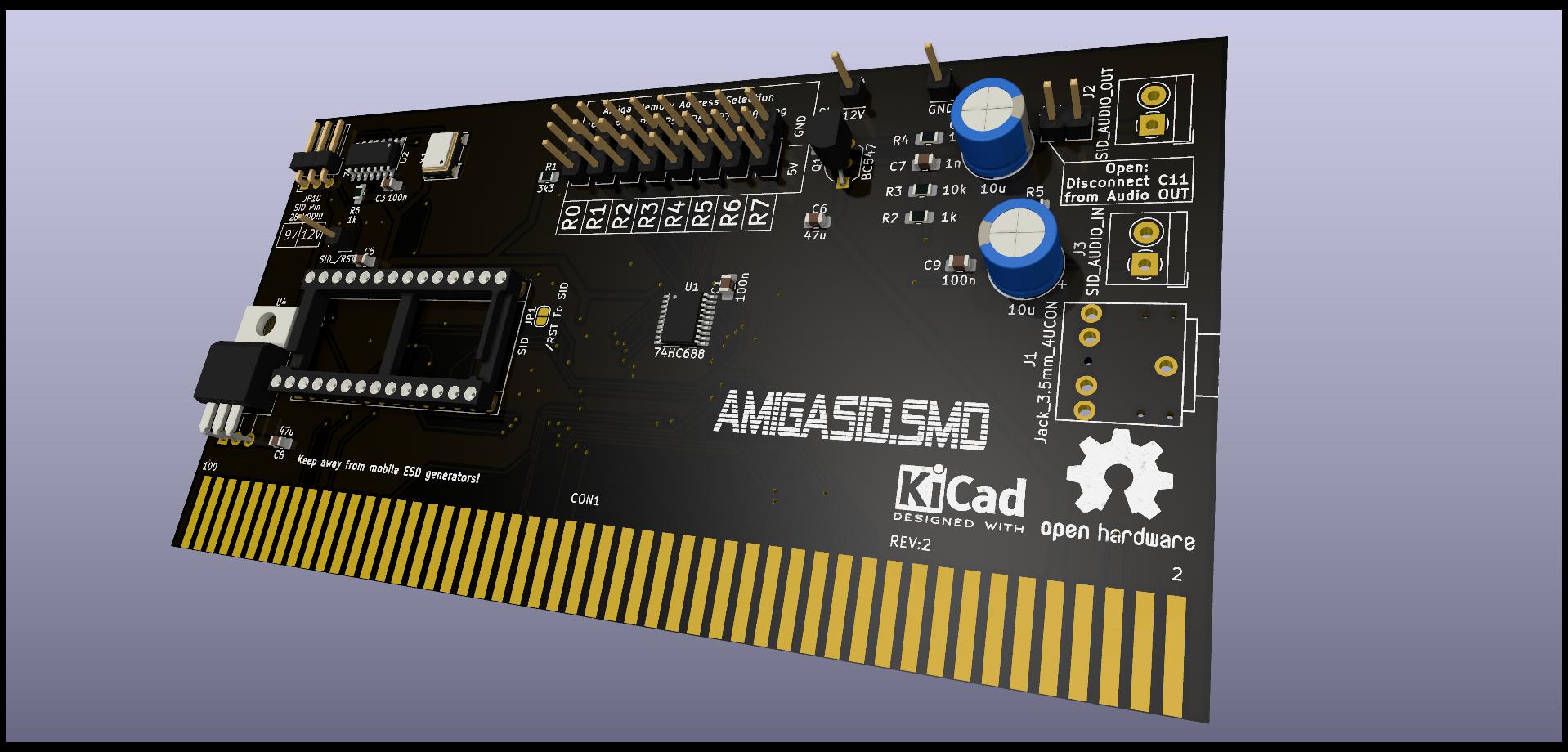 | 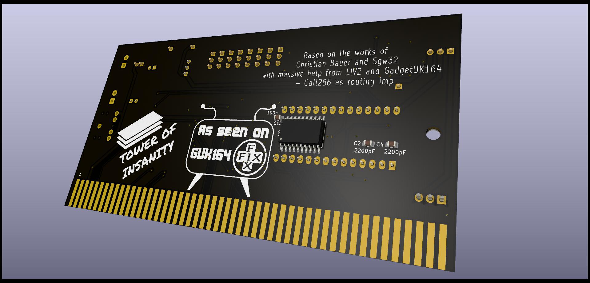 |
Forked from https://github.com/Sgw32/AmigaSID which forked from http://www.amibay.com/showthread.php?108629-Amiga-SID-player-for-Zorro-slot
Can't find the original thread on Amibay sadly, so i can't do full credits here.
Thanks to LIV2 and GadgetUK for the help in this project.
Use at your own risk!!!
As of now (06.01.2021) i haven't tested that, not even ordered boards!
Boards were kindly provided by SparxUK - Thanks mate!
The boards worked fine on my A500 with a Zorro2 adapter and a NanoSwinSID.
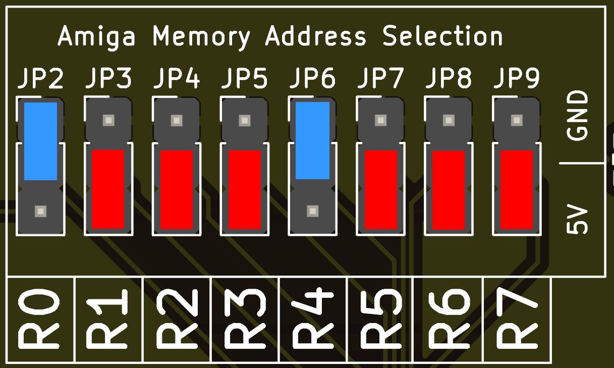
The bank of jumpers on top of the card (JP2-JP9) is used to set the memory address used by the card and the players.
Jumper setting for EE range:
| Jumper | Setting |
|---|---|
| JP2 | 1-2 (LOW) |
| JP3 | 2-3 (HIGH) |
| JP4 | 2-3 (HIGH) |
| JP5 | 2-3 (HIGH) |
| JP6 | 1-2 (LOW) |
| JP7 | 2-3 (HIGH) |
| JP8 | 2-3 (HIGH) |
| JP9 | 2-3 (HIGH) |
Here you'll find the KiCAD6 project for the board. Also there is a HTML BOM for parts placement and a jlcpcb folder with gerbers and BOM/POS for assembly (only the SMD caps/resistors, no ic's or THT parts!)
Here you'll find patched versions of players to use on the Amiga.
| Qty | Value | Footprint | References |
|---|---|---|---|
| 4 | 100n | Capacitor_SMD:C_0805_2012Metric_Pad1.18x1.45mm_HandSolder | C1, C3, C9, C13 |
| 3 | 1k | Resistor_SMD:R_0805_2012Metric_Pad1.20x1.40mm_HandSolder | R2, R4, R6 |
| 2 | 10u | Capacitor_THT:CP_Radial_D7.5mm_P2.50mm | C10, C11 |
| 2 | 2200pF | Capacitor_SMD:C_0805_2012Metric_Pad1.18x1.45mm_HandSolder | C2, C4 |
| 2 | 47u | Capacitor_SMD:C_0805_2012Metric_Pad1.18x1.45mm_HandSolder | C6, C8 |
| 1 | /RST To SID | Jumper:SolderJumper-2_P1.3mm_Bridged_RoundedPad1.0x1.5mm | JP1 |
| 1 | 100k | Resistor_SMD:R_0805_2012Metric_Pad1.20x1.40mm_HandSolder | R5 |
| 1 | 10k | Resistor_SMD:R_0805_2012Metric_Pad1.20x1.40mm_HandSolder | R3 |
| 1 | 12V | Connector_PinHeader_2.54mm:PinHeader_1x01_P2.54mm_Vertical | J4 |
| 1 | 12V/9V | Connector_PinHeader_2.54mm:PinHeader_1x03_P2.54mm_Horizontal | JP10 |
| 1 | 1n | Capacitor_SMD:C_0805_2012Metric_Pad1.18x1.45mm_HandSolder | C7 |
| 1 | 22u | Capacitor_SMD:C_0805_2012Metric_Pad1.18x1.45mm_HandSolder | C5 |
| 1 | 3k3 | Resistor_SMD:R_0805_2012Metric_Pad1.20x1.40mm_HandSolder | R1 |
| 1 | 470p | Capacitor_SMD:C_0805_2012Metric_Pad1.18x1.45mm_HandSolder | C12 |
| 1 | 74HC245 | Package_SO:SOIC-20W_7.5x12.8mm_P1.27mm | U5 |
| 1 | 74HC688 | Package_SO:TSSOP-20_4.4x6.5mm_P0.65mm | U1 |
| 1 | 74LS00 | Package_SO:SOIC-14_3.9x8.7mm_P1.27mm | U2 |
| 1 | AudioJack3 | Audio_More:Jack_3.5mm_4UCON | J1 |
| 1 | BC547 | Package_TO_SOT_THT:TO-92_Inline_Wide | Q1 |
| 1 | Disconnect C11 from Audio OUT | Connector_PinHeader_2.54mm:PinHeader_1x02_P2.54mm_Vertical | JP11 |
| 1 | GND | Connector_PinHeader_2.54mm:PinHeader_1x01_P2.54mm_Vertical | J5 |
| 1 | JPR0 | Connector_PinHeader_2.54mm:PinHeader_1x03_P2.54mm_Vertical | JP2 |
| 1 | JPR1 | Connector_PinHeader_2.54mm:PinHeader_1x03_P2.54mm_Vertical | JP3 |
| 1 | JPR2 | Connector_PinHeader_2.54mm:PinHeader_1x03_P2.54mm_Vertical | JP4 |
| 1 | JPR3 | Connector_PinHeader_2.54mm:PinHeader_1x03_P2.54mm_Vertical | JP5 |
| 1 | JPR4 | Connector_PinHeader_2.54mm:PinHeader_1x03_P2.54mm_Vertical | JP6 |
| 1 | JPR5 | Connector_PinHeader_2.54mm:PinHeader_1x03_P2.54mm_Vertical | JP7 |
| 1 | JPR6 | Connector_PinHeader_2.54mm:PinHeader_1x03_P2.54mm_Vertical | JP8 |
| 1 | JPR7 | Connector_PinHeader_2.54mm:PinHeader_1x03_P2.54mm_Vertical | JP9 |
| 1 | LM7809_TO220 | Package_TO_SOT_THT:TO-220-3_Horizontal_TabDown | U4 |
| 1 | SG-7050CCN | Oscillator:Oscillator_SMD_SeikoEpson_SG8002CA-4Pin_7.0x5.0mm | X1 |
| 1 | SID | Package_DIP:DIP-28_W15.24mm_Socket_LongPads | U3 |
| 1 | SID_/RST | Connector_PinHeader_2.54mm:PinHeader_1x01_P2.54mm_Vertical | H1 |
| 1 | SID_AUDIO_IN | TerminalBlock_4Ucon:TerminalBlock_4Ucon_1x02_P3.50mm_Horizontal | J3 |
| 1 | SID_AUDIO_OUT | TerminalBlock_4Ucon:TerminalBlock_4Ucon_1x02_P3.50mm_Horizontal | J2 |
| 1 | ZorroII | AmigaSID:ZorroII | CON1 |
The 44 most common of 49 parts.
It measures 130 × 67.5 mm and has 2 copper layers, 1.6 mm thick.
49 parts, built around the 74HC245D, 74HC688D, 74LS00SC and BC547. The full list of its parts is on this page, with links to each part's symbol and footprint where PCBKit's library has them.
From the call286/AmigaSID repository on GitHub, at the commit this page was made from: the board is Hardware/AmigaSID.kicad_pcb and its schematic Hardware/AmigaSID.kicad_sch. PCBKit opens the board in the browser, with nothing to install.
Its repository states no licence, so its author keeps all rights: ask call286 before reusing the design.


ifilot/p2000t-ram-expansion-board
RAM expansion board for the P2000T

snippyrow/-816-board
A retro computer motherboard for the W65C816S CPU. Dual-core expandable, 16mb extended memory, four expansion ports.

dennis9819/Z8C-Homebrew-Computer
To easily develop for my Z80 homebrew system, I designed a simple assempler development environment. This packs the following tasks into one script: zmac assembly object file creation (for xmodem upload) monitor file…