2 layers126 × 57 mm
Mini Oven Controller
MAWoodMain/ESP-Reflow-Oven
A retro fit of a Lidl middle aisle mini oven into a home reflow oven
46 parts2MIT

 C3MA/MrReflow
To achieve that, readings from a thermocouple are used for closed loop temperature control of the target board. The controller does it's best to follow a preconfigured temperature profile for a particular SMT soldering.
MrReflow is an open-source printed circuit board by C3MA, from the C3MA/MrReflow repository on GitHub, published under the GPL-3.0 licence. It is a 2-layer board of 55 × 96 mm with 28 parts on 43 nets, routed with 154 tracks and 20 vias.
It is built around the ESP32-WROOM-32D, IRM-05-5 and AMS1117-3.3, with the WS2812B among its other parts. Its parts include 11 capacitors, 5 resistors, 2 ICs, 2 connectors and 1 diode. It belongs with the ESP32 boards of this library.


Firmware for SMT reflow controller.
!!! WARNING: This project deals with mains power and high current !!! Please be careful if you wish to replicate any of it's functionality and never work on a PCB or any open wires that are connected to the mains ! Author has no responsibility for your safety and wellbeing, so please take care of yourself.
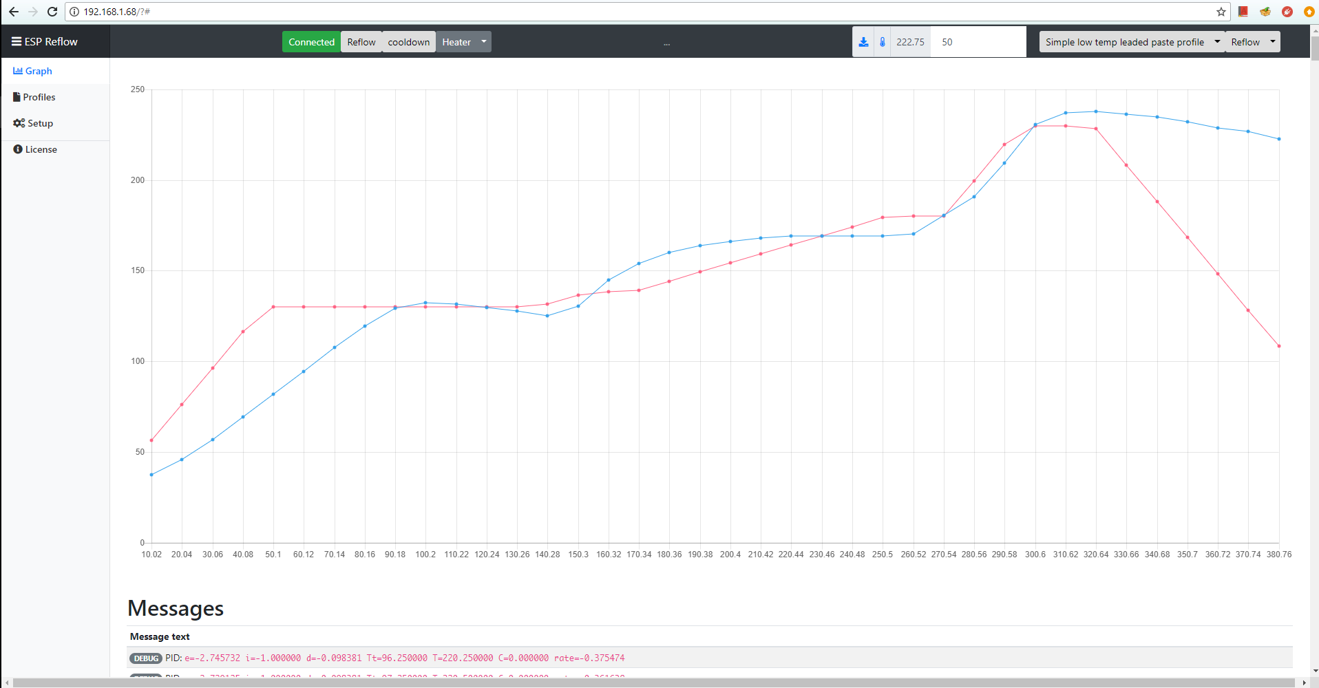
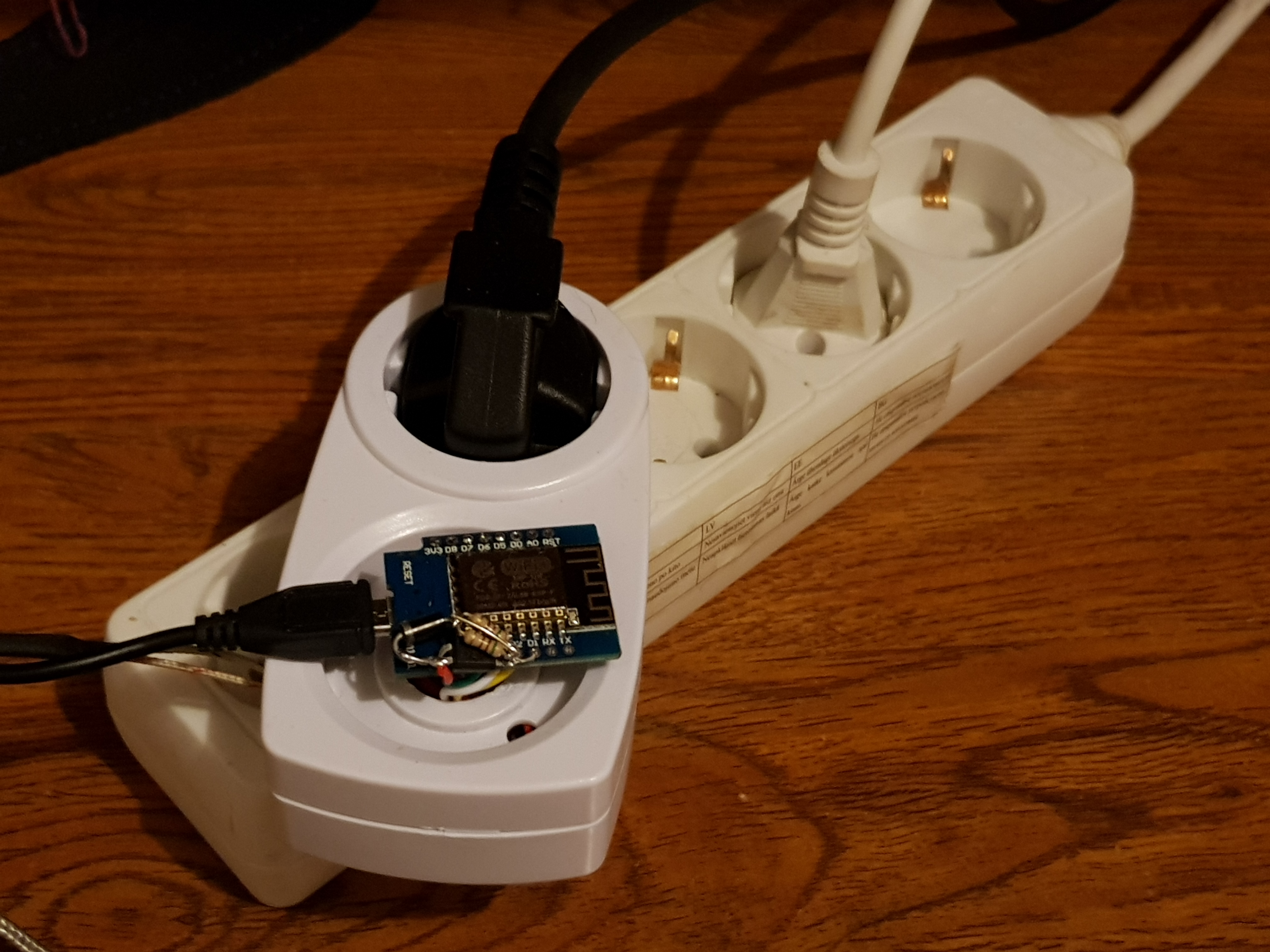
The purpose of this project is to control a heater of any sort to facilitate SMT reflow soldering utilizing a predefined temperature profile. Control of the heater is performed by ESP8266 or ESP32 chip via Web UI over WiFi.
To achieve that, readings from a thermocouple are used for closed loop temperature control of the target board. The controller does it's best to follow a preconfigured temperature profile for a particular SMT soldering. Of course the accuracy of the temperature profile achieved is heavily dependant on the thermal properties of the heating element, environment, the boards, etc. The controller tries to compensate for that by the means of a PID controller which has to be tuned to a particular setup.


EasyEDA project page: https://easyeda.com/andrius.mikonis/ESPReflow-f4c523157afa47758e46728248cdb19b
#define thermoDO 13 // D7
#define thermoCS 12 // D6
#define thermoCLK 14 // D5
#define relay 4 // D2Angular front end source is in web-src-angular folder and should be built using nodejs. After binaries are built,
they should be gzipped and copied into data/web folder before uploading.
Backend is implemented using Arduino SDK and built using PlatformIO. Before building, please copy src/sample_wificonfig.h
to src/wificonfig.h and add default Wireless Network configuration. You will be able to edit this configuration via Web interface later.
In this mode the controller will perform reflow algorithm following selected reflow profile. Controller will turn off the mode once the temperature reaches safe values after the profile is completed.
In this mode a selected calibration algorithm will be used to find optimal PID controller parameters. Controller will turn off the mode once the temperature reaches safe values after the calibration is completed.
In this mode the controller will reach and maintain target temperature. Useful to check PID configuration. default PID configuration will be used in this mode.
There are two ways to flash the controller - via serial or via OTA.
Find RX/TX/GND pins on the board, connect your serial adapter and flash either Arduino, PlatformIO or whatever flasher you like.
NOTE: RX/TX pins are NOT 5V tolerant. Please use 3.3V serial adapter or level shifter from 5V
When the controller is first turned on it creates an AP with the name ESPReflow and the ip address 192.168.4.1. Connect to the controller, wait until the page loads and go to Setup, enter WiFi SSID and credentials. Save the configuration and reboot.
After this is done it will connect to the specified WiFi AP and will register it's own domain as ReflowControl.local.
Tuning and operation of the controller can then be done.
You can upload a firmware binary using Setup - just upload the new firmware on the WebUI.
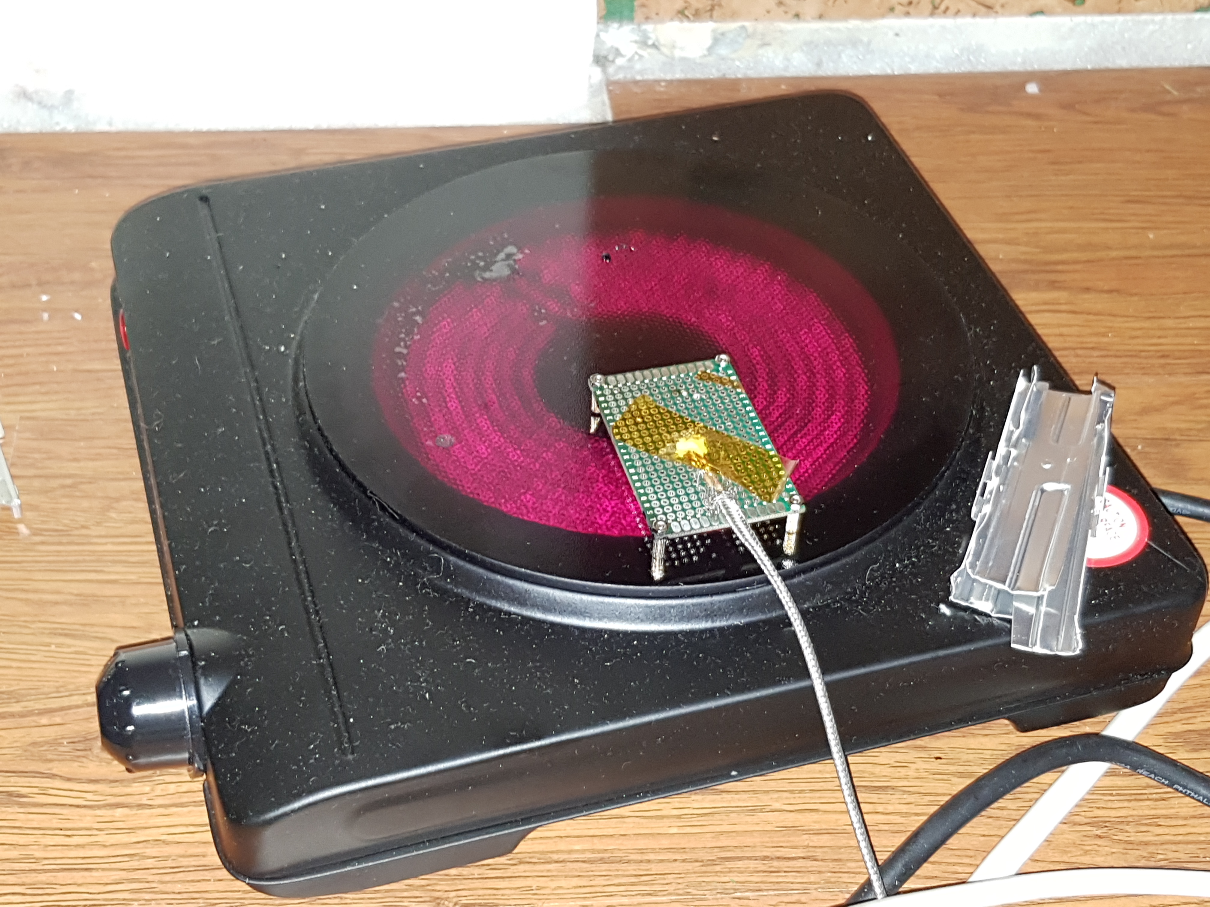
Thermocouple must be placed on a dummy board, that would approximately resemble the target boards. For best results that board must be placed in a similar matter as the target board. Furthermore, since hotplates do not heat evenly(even some ovens), care must be taken to allow dummy board be heated the same way as the target board(i.e. it must be placed approximately the same distance and orientation as the target board in respect to the heating elements). Otherwise you may burn the target board.
PID tuning must be done for every heating device individually. You can do it by trial and error, or ESPReflow can do it for you. There are several auto tuning algorithms available (a slightly modified PID-aTune library fork):
ZIEGLER_NICHOLS_PI ZIEGLER_NICHOLS_PID TYREUS_LUYBEN_PI TYREUS_LUYBEN_PID CIANCONE_MARLIN_PI CIANCONE_MARLIN_PID AMIGOF_PI PESSEN_INTEGRAL_PID SOME_OVERSHOOT_PID NO_OVERSHOOT_PID"During development a cheap IR hot plate was used. I found that if you place your temperature probe and the boards on the hot plate itself it would be very hard to control the temperature of the board properly. So, I used aluminium raisers, that raise the board around 5-10mm from the hot plate so that IR radiation would heat the boards instead of the glass plate.
| Qty | Value | Footprint | References |
|---|---|---|---|
| 4 | 1k | Resistor_SMD:R_0805_2012Metric | R13, R14, R15, R17 |
| 4 | 47uF | Capacitor_SMD:C_0805_2012Metric | C8, C9, C10, C11 |
| 3 | 100n | Capacitor_SMD:C_0805_2012Metric | C1, C2, C5 |
| 3 | 22uf | Capacitor_SMD:C_0805_2012Metric | C3, C4, C6 |
| 1 | 10k | Resistor_SMD:R_0805_2012Metric | R16 |
| 1 | 22uF | Capacitor_SMD:C_0603_1608Metric | C7 |
| 1 | AMS1117-3.3 | Package_TO_SOT_SMD:SOT-223-3_TabPin2 | U1 |
| 1 | Boot | Button_Switch_SMD:SW_SPST_CK_RS282G05A3 | Boot1 |
| 1 | Conn_01x02_Male | Connector_Phoenix_MSTB:PhoenixContact_MSTBA_2,5_2-G-5,08_1x02_P5.08mm_Horizontal | J1 |
| 1 | Conn_01x03_Female | Connector_PinHeader_2.54mm:PinHeader_1x03_P2.54mm_Vertical | J2 |
| 1 | Conn_01x04_Male | Connector_PinHeader_2.54mm:PinHeader_1x04_P2.54mm_Vertical | Display1 |
| 1 | Conn_01x05_Female | Connector_PinHeader_2.54mm:PinHeader_1x05_P2.54mm_Vertical | Thermocouple1 |
| 1 | ESP32-WROOM-32D | RF_Module:ESP32-WROOM-32 | U4 |
| 1 | IRM-05-5 | Converter_ACDC:Converter_ACDC_MeanWell_IRM-05-xx_THT | PS1 |
| 1 | SW_Push | Button_Switch_SMD:SW_SPST_CK_RS282G05A3 | Reset1 |
| 1 | WS2812B | LED_SMD:LED_WS2812B_PLCC4_5.0x5.0mm_P3.2mm | D1 |
The 26 most common of 28 parts.
It measures 55 × 96 mm and has 2 copper layers, 1.6 mm thick.
28 parts, built around the ESP32-WROOM-32D, IRM-05-5, AMS1117-3.3 and WS2812B. The full list of its parts is on this page, with links to each part's symbol and footprint where PCBKit's library has them.
From the C3MA/MrReflow repository on GitHub, at the commit this page was made from: the board is board/board/MrReflow.kicad_pcb and its schematic board/board/MrReflow.kicad_sch. PCBKit opens the board in the browser, with nothing to install.
Its repository publishes it under the GPL-3.0 licence: you may reuse it on that licence's terms (keep the author's notice, and for a copyleft licence share your changes alike).
MAWoodMain/ESP-Reflow-Oven
A retro fit of a Lidl middle aisle mini oven into a home reflow oven

freezweb/de.freezweb.heizungssteuerung
Dieses Verzeichnis enthaelt den KiCad-Startentwurf fuer die dezentrale Pumpengruppen-Platine:


CommanderRedYT/ws2812-clock
A simple pcb clock using ws2812 in 7-segment form


Rikeroo/habit-reminder
Low energy physical habit reminder, using RGB LEDs, a small task screen and tactile switches to build useful habits and get tasks done