2 layers80 × 50 mm
C3lingo unit mix io
c3lingo/c3lingo-interpreter-unit
A customized audio mixer and personal monitoring console for simultaneous interpreters.
46 parts7CC-BY-SA-4.0

 c3lingo/c3lingo-interpreter-unit7
A customized audio mixer and personal monitoring console for simultaneous interpreters.
C3lingo unit channel mixer is an open-source printed circuit board by c3lingo, from the c3lingo/c3lingo-interpreter-unit repository on GitHub, published under the CC-BY-SA-4.0 licence. It is a 2-layer board of 75 × 90 mm with 103 parts on 66 nets, routed with 515 tracks and 68 vias.
It is built around the TL072, LM339 and MMBFJ113. Its parts include 40 resistors, 16 diodes, 15 capacitors, 5 ICs and 2 connectors. It belongs with the audio and music boards of this library.


c3lingo.org is doing the great job of translating many talks of the Chaos Communication Congress and other CCC-related events to multiple languages. But the required hardware for simultaneous translation is quite expensive to rent, even if it's "just" a specialized analog audio mixer.
So the idea was born to design an easy to use hardware with the special requirements of our interpreters in mind.
The hardware unit should deliver the native audio (stage/ hall mix) to the interpreter's headset and provide a sum of all interpreter's microphone to the input of the video streaming/ recording chain. Mixing of the final translated audio (ducking the native audio with the translation) will be done as part of the streaming/ recording chain, so the interpreter unit should just provide the sum of all microphones.
Normally just 2 interpreters will provide one translation, but demanding talks might require 3 people. So either 3 headphone inputs/ outputs should be provided or it must be possible to daisy-chain multiple units.
The user interface of the unit should be as simple, as possible to decrease the risk of mis-configuration. This means, that no compressor and equalizer will be added in the input group.
General requirements:
All inputs (besides the microphones) and outputs should:
This results in a signal flow like this: 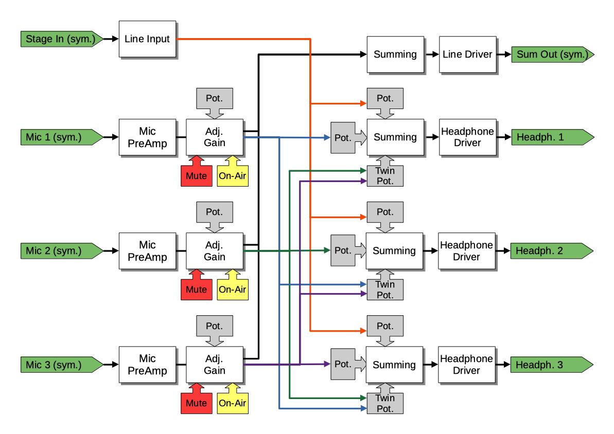
Help is always appreciated!
See electrical-design.md.
Components marked as DNP (do not populate) are needed and need to be added. The mark is just to generate the right BOM for ordering an assembled PBC with all SMD components, but no though-hole parts.
The user interface should enable the interpreters to adjust their microphone gain and headphone mix on their own. Additionally, a (permanent) on/off switch, as well as a (temporary) mute button should be present.
A possible UI layout might look like this: 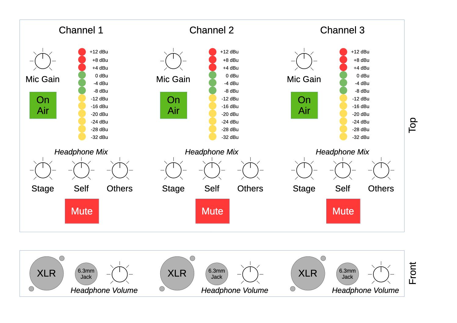
See hardware-selection.md for the selection of potentiometers and switches.
The casing should be a desk console (angled surface), ideally with space at the front to mount the headset ports (XLR and 6.3 mm jack). Since it can be quite difficult to drill holes and make the appropriate cutouts on the angled surface, we designed our own housing from bent sheet metal. See the mechanical/ directory for additional information.
PCBs are split up by channel and mounting surface, so that dimensional tolerancen between the surfaces are not that critical. The top plate should have a maximum thickness of 1.5 mm, the front and back can be slightly thicker at 2 mm. All LEDs need to be mounted with some space to the PCB surface so that they can cover the 9 mm gap to the front plate and still stick through. A mounting guide can be found at mechanical/assembly-helpers.
A dynamic microphone needs at least 50-60 dB gain in the pre-amp, because a typical signal is at about 1 - 100 uV (-118 to -78 dBu or -120 to -80 dBV).
Line level in professional audio gear is at +4 dBu, which is 1.228 V (RMS). Because 0 dBu is defined as 1 mW at a load of 600 Ohm, which needs a voltage of 0.77 V. Increasing the voltage by a factor of 10 is an amplification of 20 dB.
| Qty | Value | Footprint | References |
|---|---|---|---|
| 12 | 150R | Resistor_SMD:R_0805_2012Metric_Pad1.20x1.40mm_HandSolder | R310, R311, R312, R313, R314, R315, R316, R317, R318, R319, R320, R321 |
| 10 | 100nF | Capacitor_SMD:C_0603_1608Metric_Pad1.08x0.95mm_HandSolder | C303, C304, C306, C307, C308, C309, C310, C311, C314, C315 |
| 6 | ye | LED_THT:LED_Rectangular_W5.0mm_H2.0mm | D302, D303, D304, D305, D306, D307 |
| 4 | 1M | Resistor_SMD:R_0805_2012Metric_Pad1.20x1.40mm_HandSolder | R306, R337, R338, R339 |
| 4 | 50K log. | c3lingo_unit-footprints:Potentiometer_CUI_PTN09X_Single_Vertical | RV301, RV302, RV303, RV304 |
| 4 | MountingHole | MountingHole:MountingHole_3.2mm_M3 | H301, H302, H303, H304 |
| 3 | 1N4148 | Diode_SMD:D_SOD-123 | D314, D315, D316 |
| 3 | 22K | Resistor_SMD:R_0805_2012Metric_Pad1.20x1.40mm_HandSolder | R301, R302, R305 |
| 3 | LM339 | Package_SO:SOIC-14_3.9x8.7mm_P1.27mm | U302, U303, U304 |
| 3 | gn | LED_THT:LED_Rectangular_W5.0mm_H2.0mm | D308, D309, D310 |
| 3 | rd | LED_THT:LED_Rectangular_W5.0mm_H2.0mm | D311, D312, D313 |
| 2 | 100nF C0G | Capacitor_SMD:C_1206_3216Metric_Pad1.33x1.80mm_HandSolder | C302, C312 |
| 2 | 1uF | Capacitor_SMD:CP_Elec_4x5.8 | C305, C313 |
| 2 | 2.2K | Resistor_SMD:R_0805_2012Metric_Pad1.20x1.40mm_HandSolder | R307, R308 |
| 1 | 1.2K | Resistor_SMD:R_0603_1608Metric_Pad0.98x0.95mm_HandSolder | R331 |
| 1 | 1.5K | Resistor_SMD:R_0805_2012Metric_Pad1.20x1.40mm_HandSolder | R303 |
| 1 | 1.5K | Resistor_SMD:R_0603_1608Metric_Pad0.98x0.95mm_HandSolder | R332 |
| 1 | 100K | Resistor_SMD:R_0805_2012Metric_Pad1.20x1.40mm_HandSolder | R336 |
| 1 | 100R | Resistor_SMD:R_0603_1608Metric_Pad0.98x0.95mm_HandSolder | R324 |
| 1 | 10K | Resistor_SMD:R_0805_2012Metric_Pad1.20x1.40mm_HandSolder | R340 |
| 1 | 12K | Resistor_SMD:R_0805_2012Metric_Pad1.20x1.40mm_HandSolder | R309 |
| 1 | 150R | Resistor_SMD:R_0603_1608Metric_Pad0.98x0.95mm_HandSolder | R325 |
| 1 | 15K | Resistor_SMD:R_0603_1608Metric_Pad0.98x0.95mm_HandSolder | R335 |
| 1 | 180R | Resistor_SMD:R_0603_1608Metric_Pad0.98x0.95mm_HandSolder | R326 |
| 1 | 1K | Resistor_SMD:R_0805_2012Metric_Pad1.20x1.40mm_HandSolder | R322 |
| 1 | 2.2K | Resistor_SMD:R_0603_1608Metric_Pad0.98x0.95mm_HandSolder | R333 |
| 1 | 220R | Resistor_SMD:R_0603_1608Metric_Pad0.98x0.95mm_HandSolder | R323 |
| 1 | 270R | Resistor_SMD:R_0603_1608Metric_Pad0.98x0.95mm_HandSolder | R327 |
| 1 | 3.3K | Resistor_SMD:R_0805_2012Metric_Pad1.20x1.40mm_HandSolder | R304 |
| 1 | 3.3K | Resistor_SMD:R_0603_1608Metric_Pad0.98x0.95mm_HandSolder | R334 |
| 1 | 390R | Resistor_SMD:R_0603_1608Metric_Pad0.98x0.95mm_HandSolder | R328 |
| 1 | 470R | Resistor_SMD:R_0603_1608Metric_Pad0.98x0.95mm_HandSolder | R329 |
| 1 | 680R | Resistor_SMD:R_0603_1608Metric_Pad0.98x0.95mm_HandSolder | R330 |
| 1 | 680pF | Capacitor_SMD:C_0603_1608Metric_Pad1.08x0.95mm_HandSolder | C301 |
| 1 | GND | TestPoint:TestPoint_Keystone_5005-5009_Compact | TP305 |
| 1 | I/O | Connector_IDC:IDC-Header_2x05_P2.54mm_Horizontal | J303 |
| 1 | Interconnect | Connector_IDC:IDC-Header_2x04_P2.54mm_Horizontal | J301 |
| 1 | LM833-N | Package_SO:SOIC-8_3.9x4.9mm_P1.27mm | U305 |
| 1 | LOGO | c3lingo_unit-footprints:voctocat-15mm | G*** |
| 1 | LOGO | c3lingo_unit-footprints:chaosknoten-10mm | G*** |
| 1 | LOGO | c3lingo_unit-footprints:voctocat-25mm | G*** |
| 1 | LOGO | c3lingo_unit-footprints:chaosknoten-15mm | G*** |
| 1 | LOGO | c3lingo_unit-footprints:antifa-15mm | G*** |
| 1 | MMBFJ113 | Package_TO_SOT_SMD:SOT-23 | Q301 |
| 1 | MicA | TestPoint:TestPoint_THTPad_D2.0mm_Drill1.0mm | TP303 |
| 1 | MicB | TestPoint:TestPoint_THTPad_D2.0mm_Drill1.0mm | TP304 |
| 1 | MicX | TestPoint:TestPoint_THTPad_D2.0mm_Drill1.0mm | TP302 |
| 1 | Mute_X | Connector_PinHeader_2.54mm:PinHeader_1x02_P2.54mm_Horizontal | SW302 |
| 1 | OnAir_X | c3lingo_unit-footprints:SW_APEM_MHPS2273_DPDT | SW301 |
| 1 | Stage | TestPoint:TestPoint_THTPad_D2.0mm_Drill1.0mm | TP301 |
| 1 | TL072 | Package_SO:SOIC-8_3.9x4.9mm_P1.27mm | U301 |
| 1 | on-air | LED_THT:LED_D3.0mm | D301 |
The 99 most common of 103 parts.
c3lingo/c3lingo-interpreter-unit
A customized audio mixer and personal monitoring console for simultaneous interpreters.

c3lingo/c3lingo-interpreter-unit
A customized audio mixer and personal monitoring console for simultaneous interpreters.


mohanjan/Fagprojekt2022_Grp9
To deploy a docker container using the image do the following: Firstly build the image via the dockerfile calling it chisel3dev using the command below To insure the build please check that it is there when the images…

MadsRudolph/vinyl-adc
Discrete 3rd-order delta-sigma stereo audio ADC, built from op-amps and logic gates: a four-layer Raspberry Pi HAT made by PCBWay, with KiCad files, SPICE simulations and measurements


PrageethM1702/HRNSQ---Hybrid_Robotic_Nervous_System_for_Quadrupeds-
Implementation of a Hybrid Robotic Nervous System combining low-level reflex circuits and high-level AI cognition to study adaptive locomotion in quadruped robots.

SukkoPera/Raemixx500
Open Hardware Remake of the Commodore Amiga 500+ Mainboard

deimoscontrols/deimos
Realtime data acquisition and controls ecosystem, including hardware, firmware, and software.

It measures 75 × 90 mm and has 2 copper layers, 1.6 mm thick.
103 parts, built around the TL072, LM339 and MMBFJ113. The full list of its parts is on this page, with links to each part's symbol and footprint where PCBKit's library has them.
From the c3lingo/c3lingo-interpreter-unit repository on GitHub, at the commit this page was made from: the board is schematics/c3lingo_unit-assembly/c3lingo_unit-channel_mixer/c3lingo_unit-channel_mixer.kicad_pcb and its schematic schematics/c3lingo_unit-assembly/c3lingo_unit-assembly.kicad_sch. PCBKit opens the board in the browser, with nothing to install.
Its repository publishes it under the CC-BY-SA-4.0 licence: you may reuse it on that licence's terms (keep the author's notice, and for a copyleft licence share your changes alike).