2 layers30.5 × 22.9 mm
Switchbox
c0pperdragon/RGBtoHDMI_Accessories
Mechanical switchbox to select one of two 6-pin inputs to be forwarded to one Analog RGBtoHDMI.
10 parts2
 c0pperdragon/RGBtoHDMI_Accessories2
Mechanical switchbox to select one of two 6-pin inputs to be forwarded to one Analog RGBtoHDMI.
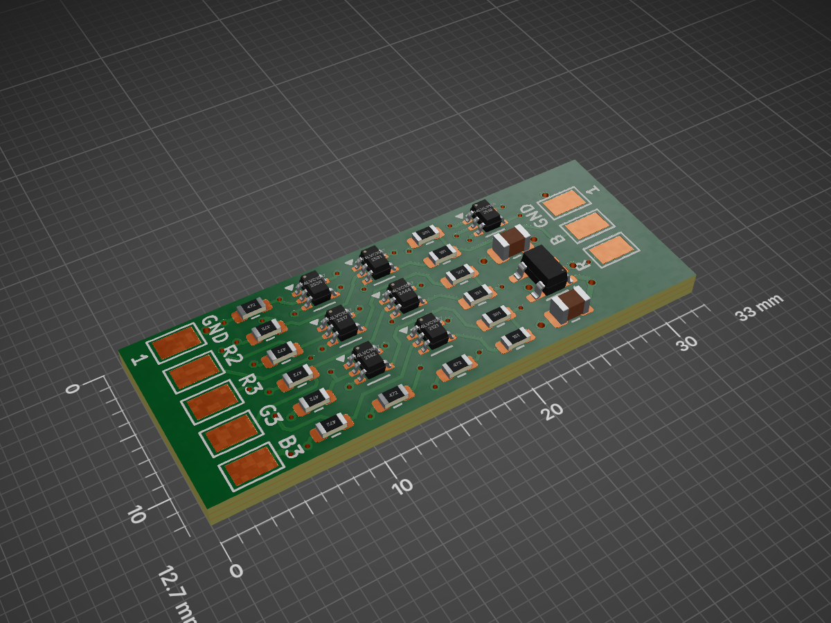
Digitaladapter is an open-source printed circuit board by c0pperdragon, from the c0pperdragon/RGBtoHDMI_Accessories repository on GitHub. It is a 4-layer board of 33 × 12.7 mm with 39 parts on 28 nets, routed with 217 tracks and 48 vias.
It is built around the 74LVC1G17Z, 74LVC1G86Z and MIC5504-3.3YM5. Its parts include 14 resistors, 8 ICs and 2 capacitors.


Mechanical switchbox to select one of two 6-pin inputs to be forwarded to one Analog RGBtoHDMI.
Note that only the 3 color signals and the csync is switched. The GND and +5V pins are always connected through. Therefore do not connect two cables that provide their +5V to the RGBtoHDMI at the same time, as these would then be shorted together, which could damage either or both of the connected machines.
| Qty | Value | Footprint | References |
|---|---|---|---|
| 15 | Conn_01x01 | Library:TestPoint_Pad_2.5x1.5mm | JIN1, JIN2, JIN3, JIN4, JIN5, JIN6, JIN7, JIN8, JIN9, JOUT1, JOUT2, JOUT3, JOUT4, JOUT5, JOUT6 |
| 8 | 4k7 | Resistor_SMD:R_0603_1608Metric | R7, R8, R9, R10, R11, R12, R13, R14 |
| 6 | 74LVC1G17 | Package_TO_SOT_SMD:SOT-353_SC-70-5 | U1, U2, U3, U4, U5, U6 |
| 3 | 150 | Resistor_SMD:R_0603_1608Metric | R2, R4, R6 |
| 3 | 300 | Resistor_SMD:R_0603_1608Metric | R1, R3, R5 |
| 2 | 10uF | Capacitor_SMD:C_0805_2012Metric | C1, C2 |
| 1 | 74LVC1G86 | Package_TO_SOT_SMD:SOT-353_SC-70-5 | U7 |
| 1 | MIC5504-3.3YM5 | Package_TO_SOT_SMD:SOT-23-5 | U8 |
c0pperdragon/RGBtoHDMI_Accessories
Mechanical switchbox to select one of two 6-pin inputs to be forwarded to one Analog RGBtoHDMI.


nkrackow/SingularitySurfer-FPGA-Lock-In-Amplifier
Repository for the development of an FPGA based DSP Lock-In Amplifier

ELEC70142-VLSI-Coursework/vlsi_test_platform
Validation environment for the VLSI SoC project. This repository integrates mechanical and PCB designs for a dedicated testrig with FPGA-based gateware and Python-driven software abstractions to facilitate full-chip…

perigoso/wmo-remastered
Replacement PCB for the classic WMO (Wheel mouse Optical) by Mcrosoft


wangyeee/OpenHardware
Collections of hardware design related to my drone project.

ErichZimmer/OpenSync
An open source synchronizer for velocimetry of fluids.

earth75/atat-1800
A compact keyboard layout with the numpad on the right hand side
It measures 33 × 12.7 mm and has 4 copper layers, 1.6 mm thick.
39 parts, built around the 74LVC1G17Z, 74LVC1G86Z and MIC5504-3.3YM5. The full list of its parts is on this page, with links to each part's symbol and footprint where PCBKit's library has them.
From the c0pperdragon/RGBtoHDMI_Accessories repository on GitHub, at the commit this page was made from: the board is digitaladapter/board/digitaladapter.kicad_pcb and its schematic digitaladapter/board/digitaladapter.kicad_sch. PCBKit opens the board in the browser, with nothing to install.
Its repository states no licence, so its author keeps all rights: ask c0pperdragon before reusing the design.