
4 layers108 × 109.6 mm
BMS - PCB Files
arihant-o/IEM-Electronics
GitHub repository for the electronics projects within IEM.
139 parts

Validation environment for the VLSI SoC project. This repository integrates mechanical and PCB designs for a dedicated testrig with FPGA-based gateware and Python-driven software abstractions to facilitate full-chip characterization and functional verification of the ASIC
TestBench is an open-source printed circuit board by ELEC70142-VLSI-Coursework, from the ELEC70142-VLSI-Coursework/vlsi_test_platform repository on GitHub. It is a 4-layer board of 72 × 59 mm with 69 parts on 115 nets, routed with 844 tracks and 83 vias.
It is built around the 74LVC1G17Z, 74LVC1G04Z and MIC5504-1.2YM5-TR, with the MIC5504-3.3YM5, USBLC6-2SC6 and 54020-44030LF among its other parts. Its parts include 24 resistors, 13 capacitors, 9 ICs, 3 diodes and 3 connectors. It belongs with the fPGA and programmable logic boards of this library.


A complete hardware and software solution for bringing up and testing the VLSI SoC Project IC. This repository contains the FPGA firmware, Python host tools, and hardware design documentation.
The test platform consists of three integrated components:
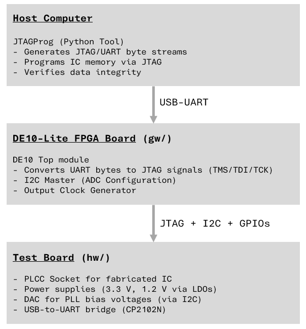
vlsi_test_platform/
├── gw/                    # FPGA Firmware (DE10-Lite)
│   ├── src/              # SystemVerilog modules
│   │   ├── DE10Top.sv    # Top-level module
│   │   ├── jtag_uart_bridge.sv
│   │   ├── jtag_engine.sv
│   │   ├── dac_commander.sv
│   │   ├── i2c_master.sv
│   │   └── uart_*.sv     # UART controller modules
│   ├── test/             # DUT (Device Under Test) bitstreams
│   └── README.md         # FPGA documentation
│
├── sw/                    # Host-Side Python Tools
│   ├── JTAGProg.py       # JTAG programmer and tester
│   └── README.md         # Python tool documentation
│
├── hw/                    # Test Board PCB Design
│   ├── [Schematic/Layout files]
│   └── README.md         # Hardware documentation
│
└── README.md # This file.sof file) onto the DE10-Lite using Quartus Programmer# Test mode: verify JTAG communication with a known pattern
python JTAGProg.py COM4 --test-mode --word-count 256
# Load mode: program memory from a hex file
python JTAGProg.py COM4 program.hexSee sw/README.md for full usage details.
The DE10-Lite FPGA implements:
JTAGProg.py provides:
The PCB includes:
| Qty | Value | Footprint | References |
|---|---|---|---|
| 11 | 4k2 | Resistor_SMD:R_0805_2012Metric_Pad1.20x1.40mm_HandSolder | R1, R2, R3, R4, R5, R6, R7, R8, R13, R14, R22 |
| 7 | TestPoint | TestPoint:TestPoint_Pad_D1.0mm | TP1, TP4, TP5, TP6, TP7, TP8, TP9 |
| 5 | 100n | Capacitor_SMD:C_0805_2012Metric_Pad1.18x1.45mm_HandSolder | C5, C6, C7, C11, C12 |
| 3 | 10u | Capacitor_SMD:C_0805_2012Metric_Pad1.18x1.45mm_HandSolder | C3, C10, C13 |
| 3 | 1u | Capacitor_SMD:C_0805_2012Metric_Pad1.18x1.45mm_HandSolder | C1, C2, C4 |
| 3 | 330R | Resistor_SMD:R_0805_2012Metric_Pad1.20x1.40mm_HandSolder | R9, R15, R16 |
| 3 | LED | LED_SMD:LED_0805_2012Metric_Pad1.15x1.40mm_HandSolder | D1, D2, D3 |
| 2 | 100R | Resistor_SMD:R_0805_2012Metric_Pad1.20x1.40mm_HandSolder | R11, R12 |
| 2 | 33R | Resistor_SMD:R_0805_2012Metric_Pad1.20x1.40mm_HandSolder | R23, R24 |
| 2 | 5.1k | Resistor_SMD:R_0805_2012Metric_Pad1.20x1.40mm_HandSolder | R17, R18 |
| 2 | 6p | Capacitor_SMD:C_0805_2012Metric_Pad1.18x1.45mm_HandSolder | C8, C9 |
| 2 | Jumper_3_Open | Connector_PinHeader_2.54mm:PinHeader_1x03_P2.54mm_Vertical | JP1, JP2 |
| 2 | SolderJumper_3_Open | Jumper:SolderJumper-3_P1.3mm_Open_RoundedPad1.0x1.5mm | JP4, JP5 |
| 2 | ~ | Connector_PinHeader_2.54mm:PinHeader_2x20_P2.54mm_Vertical | U1, U2 |
| 1 | 0R | Resistor_SMD:R_0805_2012Metric_Pad1.20x1.40mm_HandSolder | R21 |
| 1 | 1k | Resistor_SMD:R_0805_2012Metric_Pad1.20x1.40mm_HandSolder | R10 |
| 1 | 22.1k | Resistor_SMD:R_0805_2012Metric_Pad1.20x1.40mm_HandSolder | R19 |
| 1 | 47.5k | Resistor_SMD:R_0805_2012Metric_Pad1.20x1.40mm_HandSolder | R20 |
| 1 | 54020-44030LF | Footprints:5402044030LF | J4 |
| 1 | 74LVC1G04 | Package_TO_SOT_SMD:SOT-353_SC-70-5 | U8 |
| 1 | 74LVC1G17 | Package_TO_SOT_SMD:SOT-353_SC-70-5 | U9 |
| 1 | ADE04S04 | Footprints:ADE04S04 | S1 |
| 1 | CP2102N-Axx-xQFN24 | Package_DFN_QFN:QFN-24-1EP_4x4mm_P0.5mm_EP2.6x2.6mm | U6 |
| 1 | Conn_01x02_Socket | Footprints:CTB30512BK | J2 |
| 1 | Crystal_GND24 | Crystal:Crystal_SMD_3225-4Pin_3.2x2.5mm | Y1 |
| 1 | DAC7578xRGE | Package_DFN_QFN:QFN-24-1EP_4x4mm_P0.5mm_EP2.6x2.6mm | U5 |
| 1 | LOGO | LOGO | G*** |
| 1 | MIC5504-1.2YM5 | Package_TO_SOT_SMD:SOT-23-5 | U3 |
| 1 | MIC5504-3.3YM5 | Package_TO_SOT_SMD:SOT-23-5 | U4 |
| 1 | MountingHole | MountingHole:MountingHole_3.2mm_M3 | H1 |
| 1 | SLW-118562-4A-N-D | Footprints:SLW1185624AND | S2 |
| 1 | TS04-66-73-BK-100-SMT | Footprints:TS046665BK160SMT | SW1 |
| 1 | USBLC6-2SC6 | Package_TO_SOT_SMD:SOT-23-6 | U7 |
| 1 | USB_C_Receptacle_USB2.0_16P | Connector_USB:USB_C_Receptacle_GCT_USB4105-xx-A_16P_TopMnt_Horizontal | J5 |
arihant-o/IEM-Electronics
GitHub repository for the electronics projects within IEM.


osmocom/osmo-e1-hardware
Osmocom open source E1 (TDM) hardware; mirror of https://gitea.osmocom.org/retronetworking/osmo-e1-hardware

asinghani/ibm-5151-controller
Building a VT100 emulator out of an IBM 5151 monitor and an FPGA


It measures 72 × 59 mm and has 4 copper layers, 1.6 mm thick.
69 parts, built around the 74LVC1G17Z, 74LVC1G04Z, MIC5504-1.2YM5-TR and MIC5504-3.3YM5. The full list of its parts is on this page, with links to each part's symbol and footprint where PCBKit's library has them.
From the ELEC70142-VLSI-Coursework/vlsi_test_platform repository on GitHub, at the commit this page was made from: the board is hw/kicad/TestBench.kicad_pcb and its schematic hw/kicad/TestBench.kicad_sch. PCBKit opens the board in the browser, with nothing to install.
Its repository states no licence, so its author keeps all rights: ask ELEC70142-VLSI-Coursework before reusing the design.