2 layers103.3 × 39.9 mm

 c0pperdragon/HotPlate48
Cheap DIY solution to make a heater for hot-plate soldering.
Hpboard is an open-source printed circuit board by c0pperdragon, from the c0pperdragon/HotPlate repository on GitHub. It is a 2-layer board of 60 × 100 mm with 32 parts on 26 nets, routed with 204 tracks and 16 vias.
It is built around the ATTINY1604-SSF, TMCS1108A4BQD and SI4435FDY, with the T2N7002AK,LM among its other parts. Its parts include 7 resistors, 6 capacitors, 4 transistors, 3 ICs and 1 switch. It belongs with the AVR (ATmega, ATtiny) boards of this library.


Cheap DIY solution to make a heater for hot-plate soldering.
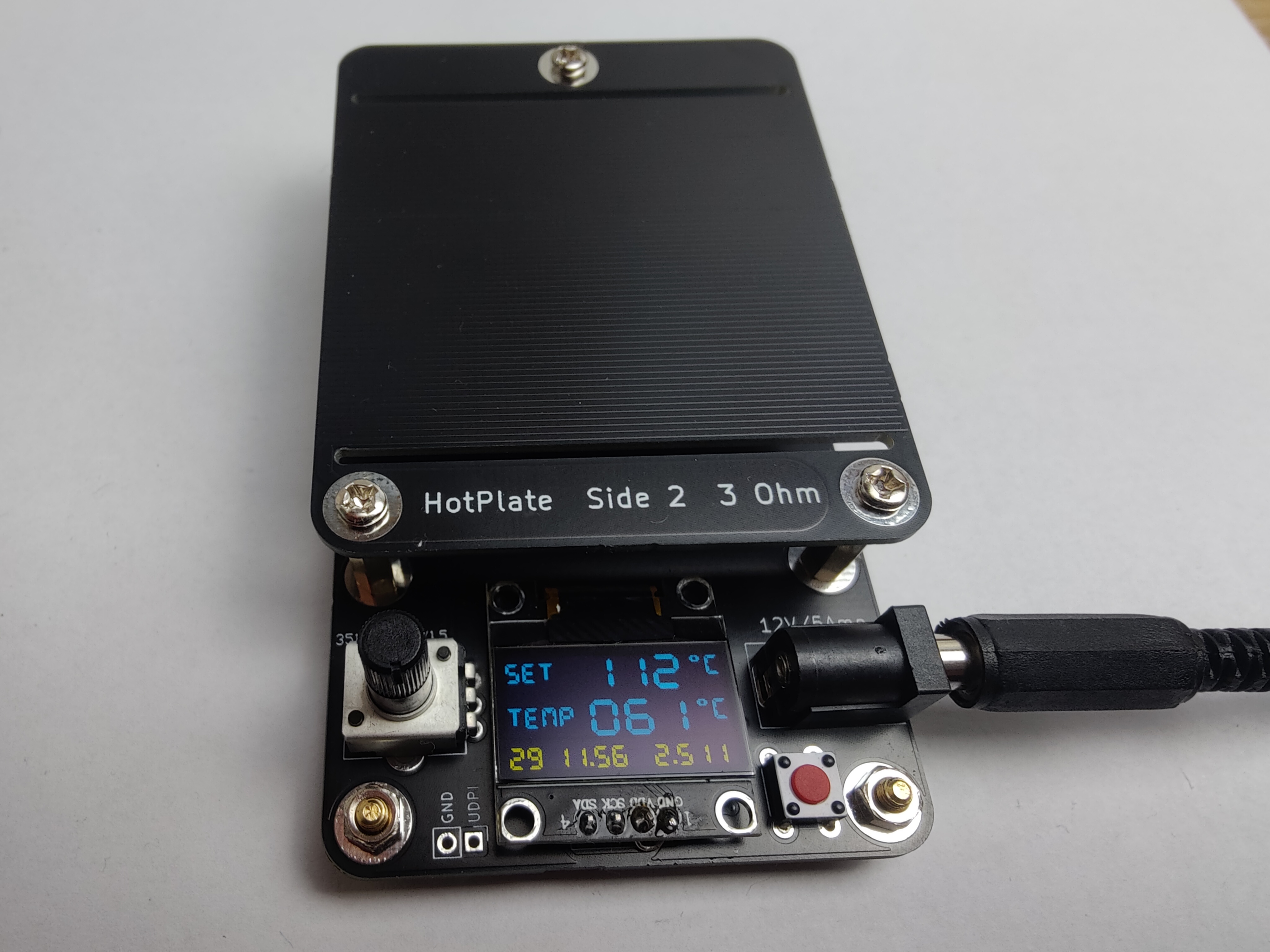
To switch the device between centigrade and fahrenheit, press the power button more than 3 seconds when turning it on.
The numbers in the bottom area are used to understand the internal working and show the following things:
The heater plate contains two copper traces (one at the top and one at the bottom) that can individually be connected to the supply voltage. These traces have a resistance of about 3.5 ohm each (within manufacturing tolerances) and will produce the heat for the process. For fine control of the output power, the controller circuit will quickly turn each heater trace on and off.
To receive feeedback about the current temperature, the controller circuit contains a Hall-effect sensor to monitor the electric current running through the top heater trace. Combined with the voltage that is also monitored, the resistance of this trace can be computed. As the specific resistance of copper changes with temperature, the current temperature can be computed.
Note that due to tolerances in PCB manufacturing and in the electronic parts, the temperature measurement may be not very precise. You will need to experimentally find the best temperature setting for your specific application.
The repeated thermal stress on the heater will probably cause it to get damaged eventually. In this case it is quite easy to have a replacement PCB made using the Gerber files. As you will probably get multiple parts from your manufacturer, this should then last for a considerable time. You can also just turn over the heater plate if the top surface gets scratched or is otherwise worn out, so you can continue to use it.
| Qty | Value | Footprint | References |
|---|---|---|---|
| 7 | Conn_01x01 | Library:MountingHole_3.2mm_Large | JBOTTOM1, JGND1, JSTAND1, JSTAND2, JSTAND3, JSTAND4, JTOP1 |
| 4 | 10k | Resistor_SMD:R_0805_2012Metric_Pad1.20x1.40mm_HandSolder | R1, R2, R3, R4 |
| 3 | 100nF | Capacitor_SMD:C_0603_1608Metric_Pad1.08x0.95mm_HandSolder | C3, C5, C6 |
| 2 | 10uF | Capacitor_SMD:C_0805_2012Metric_Pad1.18x1.45mm_HandSolder | C1, C2 |
| 2 | 1k | Resistor_SMD:R_0805_2012Metric_Pad1.20x1.40mm_HandSolder | R6, R9 |
| 2 | Si4435FDY | Package_SO:SOIC-8_3.9x4.9mm_P1.27mm | Q3, Q4 |
| 2 | T2N7002AK | Package_TO_SOT_SMD:SOT-23 | Q1, Q2 |
| 1 | 100uF | Capacitor_Tantalum_SMD:CP_EIA-3528-21_Kemet-B_Pad1.50x2.35mm_HandSolder | C4 |
| 1 | 2k2 | Resistor_SMD:R_0805_2012Metric_Pad1.20x1.40mm_HandSolder | R5 |
| 1 | ATtiny1604-SS | Package_SO:SOIC-14_3.9x8.7mm_P1.27mm | U2 |
| 1 | Barrel_Jack_Switch | Connector_BarrelJack:BarrelJack_Horizontal | JPWR1 |
| 1 | Conn_01x02 | Connector_PinHeader_2.54mm:PinHeader_1x02_P2.54mm_Vertical | JUDPI1 |
| 1 | Conn_01x04 | Connector_PinHeader_2.54mm:PinHeader_1x04_P2.54mm_Vertical | JDISPLAY1 |
| 1 | FSM2JAH | Button_Switch_THT:SW_PUSH_6mm | SW1 |
| 1 | PTV09A-1 | Potentiometer_THT:Potentiometer_Bourns_PTV09A-1_Single_Vertical | RV1 |
| 1 | TLV1117-50 | Package_TO_SOT_SMD:SOT-223-3_TabPin2 | U3 |
| 1 | TMCS1108A4B | Package_SO:SOIC-8_3.9x4.9mm_P1.27mm | U1 |
It measures 60 × 100 mm and has 2 copper layers, 1.6 mm thick.
32 parts, built around the ATTINY1604-SSF, TMCS1108A4BQD, SI4435FDY and T2N7002AK,LM. The full list of its parts is on this page, with links to each part's symbol and footprint where PCBKit's library has them.
From the c0pperdragon/HotPlate repository on GitHub, at the commit this page was made from: the board is hpboard/hpboard.kicad_pcb and its schematic heater/heater.kicad_sch. PCBKit opens the board in the browser, with nothing to install.
Its repository states no licence, so its author keeps all rights: ask c0pperdragon before reusing the design.


GadgetReboot/ATTiny_LFO
Dual low frequency oscillators using ATTiny and MCP4725 DACs

