Skip to the content
PCBKitNew board
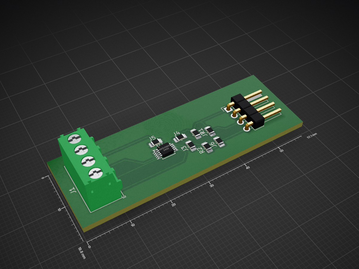
2 layersJumperTest, the printed circuit board in 3D

JumperTest

c-/JumperTest

quick and dirty test of doing sane 1-sided PCB's using a easy-to-add jumper symbol

Copper layers
2
Thickness
1.6 mm
Parts
10
Nets
9
Pads
32
Tracks, vias
57, 0
Pours
1
Routed
Yes
KiCad
KiCad 7 (file 20221018)
Created
14 Jun 2025
Updated
14 Jun 2025

Overview

JumperTest is an open-source printed circuit board by c-, from the c-/JumperTest repository on GitHub. It is a 2-layer board with 10 parts on 9 nets, routed with 57 tracks and 0 vias.

It is built around the ADS1015IDGS. Its parts include 7 connectors, 2 resistors and 1 IC.

Main components

1

README

README.md

JumperTest

quick and dirty test of doing sane 1-sided PCB's using a easy-to-add jumper symbol

Parts

10
QtyValueFootprintReferences
5~Resistor_SMD:R_0805_2012Metric_Pad1.20x1.40mm_HandSolderJ3, J4, J5, J6, J7
2RResistor_SMD:R_0805_2012Metric_Pad1.20x1.40mm_HandSolderR1, R2
1ADS1015IDGSPackage_SO:TSSOP-10_3x3mm_P0.5mmU1
1Conn_01x04Connector_PinHeader_2.54mm:PinHeader_1x04_P2.54mm_HorizontalJ2
1Screw_Terminal_01x04TerminalBlock_Phoenix:TerminalBlock_Phoenix_PT-1,5-4-3.5-H_1x04_P3.50mm_HorizontalJ1

Questions

What parts does the JumperTest use?

10 parts, built around the ADS1015IDGS. The full list of its parts is on this page, with links to each part's symbol and footprint where PCBKit's library has them.

Where can I download the JumperTest KiCad files?

From the c-/JumperTest repository on GitHub, at the commit this page was made from: the board is JumperTest.kicad_pcb and its schematic JumperTest.kicad_sch. PCBKit opens the board in the browser, with nothing to install.

Can I use the JumperTest design in my own project?

Its repository states no licence, so its author keeps all rights: ask c- before reusing the design.

Similar boards

  • 4 layers145.5 × 64 mmMuffin, the printed circuit board in 3D

    Muffin

    JunOllyLi/TX_PCB

    NOTE: the latest PCB had been manufactured was v2.0. But it had the Gimbal ZH-connector reversed. The schematics and PCB drawing had been updated to v2.1 to fix that. But v2.1 had not been really manufactured yet.

    138 parts17
  • 2 layers64.8 × 62 mmSensor, the printed circuit board in 3D

    Sensor

    chukhanhhoang/SoftRoboticSetupFesto

    Code for Raspberry Pi and Matlab/Simulink

    89 parts14
  • 4 layers70.8 × 110 mmBonkulator, the printed circuit board in 3D

    Bonkulator

    shannon-greenlight/bonkulator

    Multifunction Eurorack Module

    261 parts11GPL-3.0
  • 4 layers100 × 100 mmSolar panel side Z, the printed circuit board in 3D

    Solar panel side Z

    proveskit/solar_boards

    The solar panel boards for the PROVES Kit

    45 parts4CERN-OHL-W-2.0
  • 4 layers65 × 30 mmGripper hat, the printed circuit board in 3D

    Gripper hat

    nhnifong/stringman-pcbs

    PCBs used in the Stringman robot

    56 parts3
  • 4 layers88 × 94.5 mmBattery Board V3a, the printed circuit board in 3D

    Battery Board V3a

    proveskit/battery_board

    The battery and power management board for the PROVES Kit.

    204 parts2CERN-OHL-W-2.0
  • 4 layers66.9 × 66.9 mmTemp Monitor, the printed circuit board in 3D

    Temp Monitor

    Alex-C-EE/Reliable-Temp-Monitor

    A CAN Node designed to take temperature measurement from 3 analog-output sensors and control 2x 24V fans

    127 parts1
  • 4 layers110 × 120 mmDUT Interface board v0.2, the printed circuit board in 3D

    DUT Interface board v0.2

    krishchan007/DUT_Interface_board_v0.2

    v0.2 of DUT interface board with significant changes in layout, architecture etc.

    271 parts1