2 layers43.7 × 27.9 mm
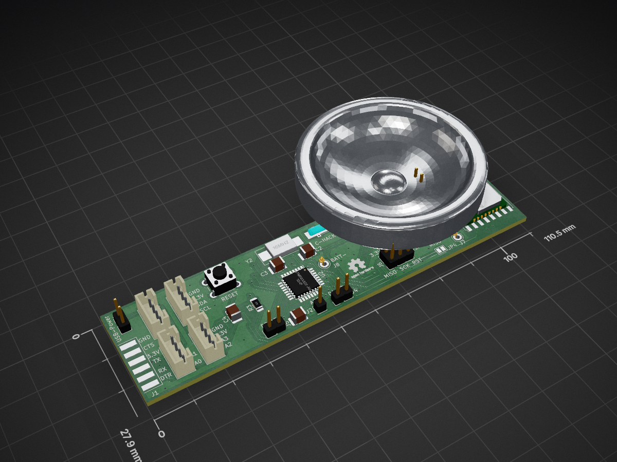
 c-hack/CaLoRa-Node1
LoRaWAN node for lowest power consumption on a battery
CaLoRa is an open-source printed circuit board by c-hack, from the c-hack/CaLoRa-Node repository on GitHub. It is a 2-layer board of 110.5 × 27.9 mm with 38 parts on 42 nets, routed with 608 tracks and 58 vias.
It is built around the ATMEGA328-AU, DS1337C# and RFM95W-868S2. Its parts include 12 connectors, 7 resistors, 5 capacitors, 3 ICs and 2 crystals. It belongs with the power and radio and wireless boards and the AVR (ATmega, ATtiny) boards of this library.


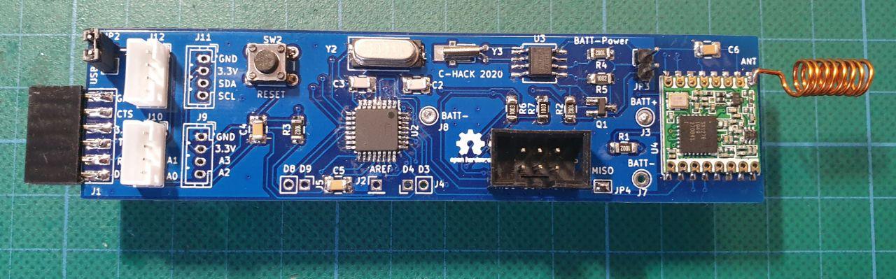
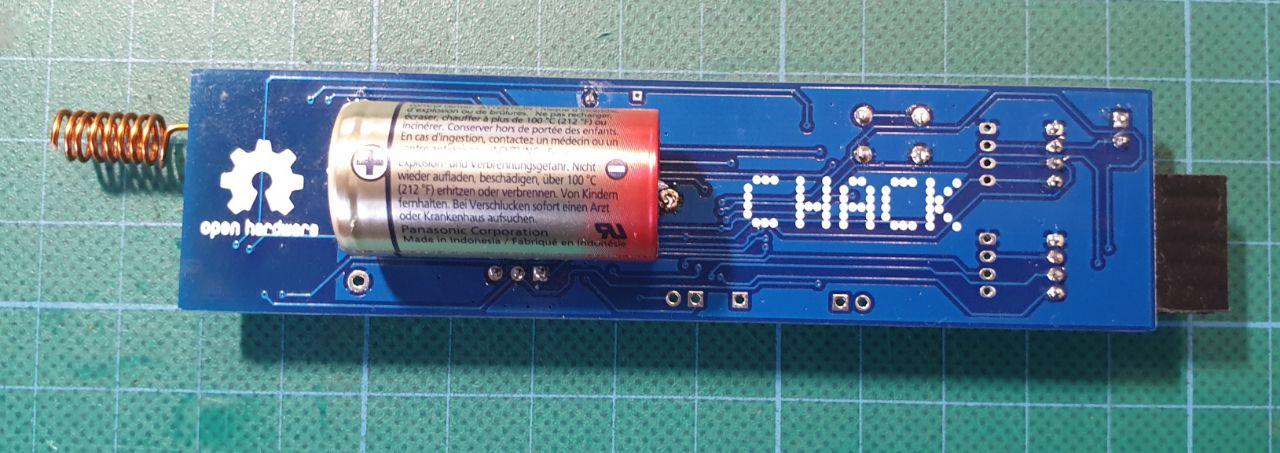
This LoRaWAN node is designed to run for long time on a battery. It uses an external RTC (DS1337) with alarm function to enable or disable the complete power supply by switching a P-MOS FET. This is the deepest sleep possible.
It uses an Atmel ATMega328 with the Arduino-UNO bootloader. The LoRAWAN is implemented with an HopeRF RFM95W module. The board implements some grove compatible connectors wuth I2C and analog inputs of the MCU.
We use the lmic software library for now but will add a wrapper to make it simpler.
| Qty | Value | Footprint | References |
|---|---|---|---|
| 4 | 10k | Resistor_SMD:R_1206_3216Metric_Pad1.42x1.75mm_HandSolder | R1, R3, R4, R5 |
| 4 | Conn_01x04_Male | Connector_JST:JST_PH_B4B-PH-K_1x04_P2.00mm_Vertical | J9, J10, J11, J12 |
| 3 | 100n | Capacitor_SMD:C_1210_3225Metric_Pad1.42x2.65mm_HandSolder | C4, C5, C6 |
| 3 | Screw_Terminal_01x01 | Connector_Pin:Pin_D1.0mm_L10.0mm_LooseFit | J3, J7, J8 |
| 2 | 100k | Resistor_SMD:R_1206_3216Metric_Pad1.42x1.75mm_HandSolder | R6, R7 |
| 2 | 22p | Capacitor_SMD:C_1210_3225Metric_Pad1.42x2.65mm_HandSolder | C2, C3 |
| 2 | Conn_01x02_Male | Connector_PinHeader_2.54mm:PinHeader_1x02_P2.54mm_Vertical | J4, J5 |
| 2 | Jumper | Connector_PinHeader_2.54mm:PinHeader_1x02_P2.54mm_Vertical | JP2, JP3 |
| 1 | 16MHz | Crystal:Crystal_SMD_7050-2Pin_7.0x5.0mm_HandSoldering | Y2 |
| 1 | 22k | Resistor_SMD:R_1206_3216Metric_Pad1.42x1.75mm_HandSolder | R2 |
| 1 | 32kHz | Crystal:Crystal_DS26_D2.0mm_L6.0mm_Horizontal_1EP_style2 | Y3 |
| 1 | ATmega328-AU | Package_QFP:TQFP-32_7x7mm_P0.8mm | U2 |
| 1 | AVR-ISP-6 | Connector_PinHeader_2.54mm:PinHeader_2x03_P2.54mm_Vertical | J6 |
| 1 | Conn_01x01_Male | Connector_PinHeader_2.54mm:PinHeader_1x01_P2.54mm_Vertical | J2 |
| 1 | Conn_01x06_Male | KiCAD-Ralf:TestPoint_Pad_6x1.5x4.0mm | J1 |
| 1 | DS1337 | Package_SO:SO-8_5.3x6.2mm_P1.27mm | U3 |
| 1 | Q_PMOS_GSD | Package_TO_SOT_SMD:SOT-23_Handsoldering | Q1 |
| 1 | RFM95W-868S2 | RF_Module:HOPERF_RFM9XW_SMD | U4 |
| 1 | SW_Push_Dual | Button_Switch_THT:SW_PUSH_6mm_H5mm | SW2 |
| 1 | SolderJumper_2_Open | Jumper:SolderJumper-2_P1.3mm_Open_Pad1.0x1.5mm | JP4 |
The 34 most common of 38 parts.
It measures 110.5 × 27.9 mm and has 2 copper layers, 1.6 mm thick.
38 parts, built around the ATMEGA328-AU, DS1337C# and RFM95W-868S2. The full list of its parts is on this page, with links to each part's symbol and footprint where PCBKit's library has them.
From the c-hack/CaLoRa-Node repository on GitHub, at the commit this page was made from: the board is KiCAD-V1-FINAL/CaLoRa.kicad_pcb. PCBKit opens the board in the browser, with nothing to install.
Its repository states no licence, so its author keeps all rights: ask c-hack before reusing the design.


mohamed-elsayed13/PCB_DESIGN_BOARDS
In this repo some simple PCB Boards designed for learning purpose.


dridri/bcflight
Raspberry Pi based drone flight controller and remote control

