2 layers43.9 × 29 mm
C64Saver2-addon
bwack/C64-Saver-bwack
C64 Saver v1 and v2 - Overvoltage protection for the C64 and its power brick.
42 parts124

 bwack/C64-Saver-bwack124
C64 Saver v1 and v2 - Overvoltage protection for the C64 and its power brick.
C64Saver2-addon is an open-source printed circuit board by bwack, from the bwack/C64-Saver-bwack repository on GitHub. It is a 2-layer board of 43.9 × 29 mm with 43 parts on 25 nets, routed with 538 tracks and 27 vias.
It is built around the ATTINY85-20SU, ACPL-217-50DE and ISO1541D. Its parts include 14 resistors, 13 capacitors, 8 ICs, 5 connectors and 1 diode. It belongs with the AVR (ATmega, ATtiny) boards of this library.


C64 Saver v1 and v2
Designed by BWACK 2018 CERN OPEN HARDWARE LICENSE v1.2 http://www.ohwr.org/
The KiCad and other design files are available on GitHub: https://github.com/bwack/
All text above must be included in any redistribution
The C64 Saver 2 is an open-source project intended to make overvoltage protection available and easy to make for anyone interested in using the old Commodore power brick together with the C64. The power brick is 30-40 years old, and it is known for failure with overvoltage. This is caused sometimes because of broken solder joints on the regulator or the regulator itself failing.
The base board is all you need for overvoltage protection. Through hole parts except for the mosfet, but it is large and easy to solder, no special tools needed other than your solder iron. The board shape fits the Hammond 1551g project case.
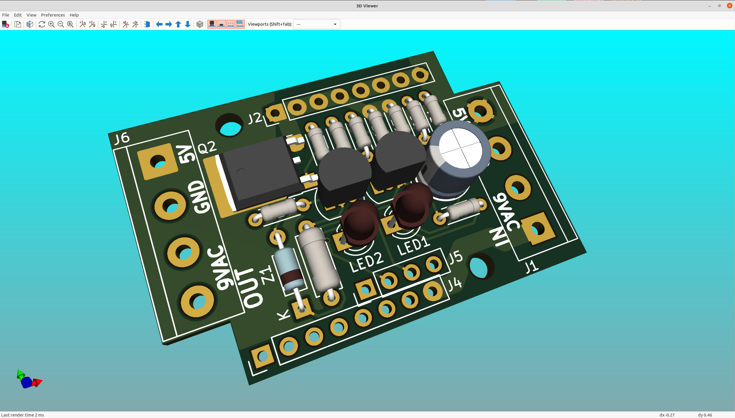
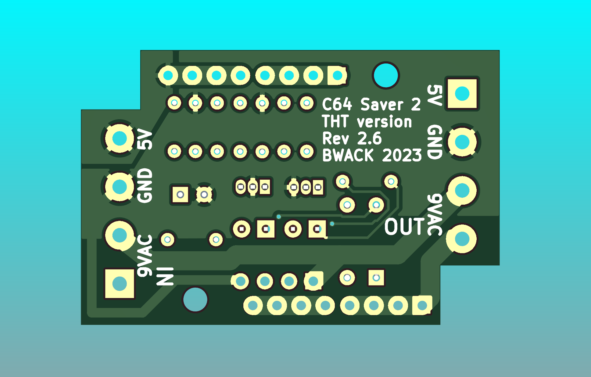
There is also a SMD version for those who like to reflow soldering.
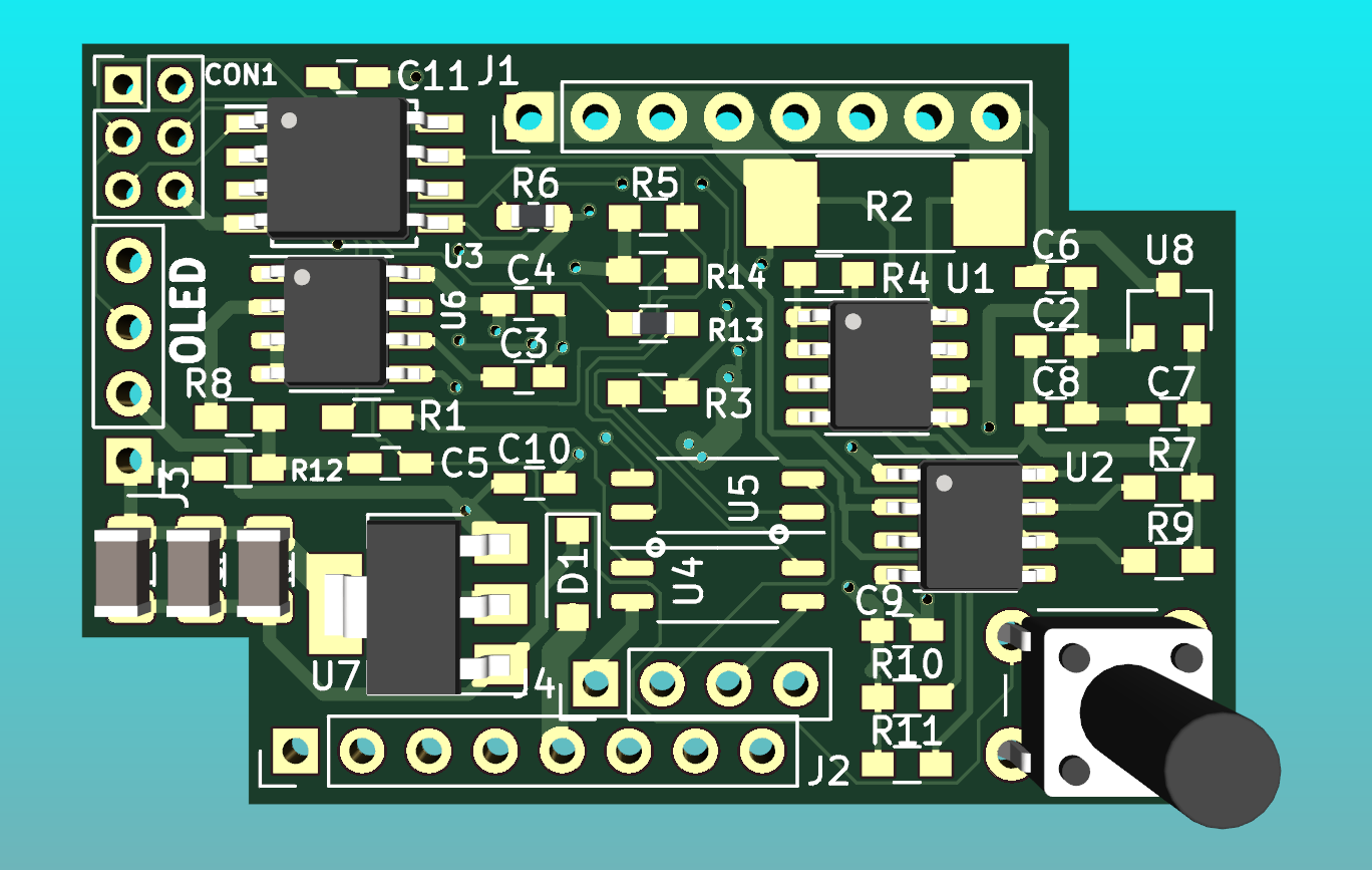
The C64 saver addon board is a hat for the base board, and adds software control, instrumentation on both ac and dc side, and an optional 128x32 OLED display. The aim for this project is to make a tool for C64 repairers. The 9VAC and 5VDC are fully isolated. Software control and instrumentation is useful if you are repairing C64s. You can set the output to shut down in case of an overcurrent condition. If an overvoltage happens you can configure the saver to auto reset or keep the power from comming back on again. There are several reasons why you might want this. C64 PSUs that need service, the capacitors are dry and the 5VDC has an AC component on it. The saver would normally just go on and off at 100Hz. The software control can detect this. The other problem is if the computer has a faulty chip that cause massive current draw on the 5V. The fuse might not blow because it is not enough, then you can configure the saver cut if you desire. I'm not gonna lie. This is my pet project, and the cost has not been a topic on my mind.
The C64 Saver Addon Board 1.4:
Youtube video of me testing the addon board installed on the C64 Saver 2.
The relay and hold board is archived in the oldfiles folder.
OCP, not robocop, but overcurrent protection. Is a new circuit that I'm working on. It has three LEDs and a button. The overvoltage protection circuit is the same as before. The overcurrent will light the yellow led and keep it lit and keep the output OFF after an overcurrent event.
I have decided to release my older C64 Saver v1. The board that fits inside a connector. Time and skill is super high on this product so be warned ! (SMD 0603, solder blob connections, tight spaces and short circuit hazards).
If you are looking for gerbers, click the releases tab. There you will find a zip file of gerber for each release.
All bill of materials (BOM) are moved into the respective project folders. I have added digikey etc order no. in the parts in the schematics such that they will show up in the interactive boms.
Here are the interactive BOMs:
ibom for C64 Saver Throughole 2.6
C64 Saver 2.6 (THT+SMD) and Addon Board 1.4 (2023-04-02)
C64 Saver 2.5 (SMD) (2020-09-13)
RelayHold 0.2 (2019-08-25)
Addon Board 1.3 (2019-05-24)
Addon Board 1.2 (2018-11-11)
C64 Saver 2.4 (2018-09-23)
Addon Board 1.1 (2018-09-23)
C64 Saver 2.3 (2018-08-18)
C64 Saver 2.2 (2018-08-16)
C64 Saver 2.1 & Addon 1.0 (2018-07-23)
C64 Saver 2.0beta & Addon 1.0beta (2018-07-02)
| Qty | Value | Footprint | References |
|---|---|---|---|
| 5 | 100n | Capacitors_SMD:C_0603_HandSoldering | C2, C5, C8, C9, C11 |
| 5 | 4k7 | Resistors_SMD:R_0603_HandSoldering | R7, R8, R9, R10, R11 |
| 4 | 1u | Capacitors_SMD:C_0603_HandSoldering | C3, C6, C7, C10 |
| 3 | 47uF | Capacitor_SMD:C_1206_3216Metric | C1, C12, C13 |
| 2 | 560 | Resistors_SMD:R_0603_HandSoldering | R1, R3 |
| 2 | ACPL-217-50DE | Package_SO:SOIC-4_4.55x2.6mm_P1.27mm | U4, U5 |
| 2 | Conn_01x08_Female | Pin_Headers:Pin_Header_Straight_1x08_Pitch2.54mm | J1, J2 |
| 1 | 0R1 | Resistors_SMD:R_2512_HandSoldering | R2 |
| 1 | 100nF | Capacitors_SMD:C_0603_HandSoldering | C4 |
| 1 | 10K | Resistors_SMD:R_0603_HandSoldering | R4 |
| 1 | 10k | Resistors_SMD:R_0603_HandSoldering | R13 |
| 1 | 1k | Resistors_SMD:R_0603_HandSoldering | R14 |
| 1 | 470 | Resistors_SMD:R_0603_HandSoldering | R12 |
| 1 | 470k | Resistors_SMD:R_0603_HandSoldering | R5 |
| 1 | 470k | Resistor_SMD:R_0603_1608Metric_Pad1.05x0.95mm_HandSolder | R6 |
| 1 | ACS712 | Package_SO:SOIC-8_3.9x4.9mm_P1.27mm | U6 |
| 1 | ATTINY85-20SU | Package_SO:SOIJ-8_5.3x5.3mm_P1.27mm | U3 |
| 1 | AVR-ISP-6 | Pin_Headers:Pin_Header_Straight_2x03_Pitch2.00mm | CON1 |
| 1 | Conn_01x04_Female | Pin_Headers:Pin_Header_Straight_1x04_Pitch2.54mm | J4 |
| 1 | Dotec SL1G | Diodes_SMD:D_SOD-123 | D1 |
| 1 | INA219xIDR-SOIC | Package_SO:SOIC-8_3.9x4.9mm_P1.27mm | U1 |
| 1 | ISO1541D | Package_SO:SOIC-8_3.9x4.9mm_P1.27mm | U2 |
| 1 | MCP1703 | Package_TO_SOT_SMD:SOT-223-3_TabPin2 | U7 |
| 1 | MCP1703 | TO_SOT_Packages_SMD:SOT-23 | U8 |
| 1 | OLED_128x32_Conn_01x04_Male | Pin_Headers:Pin_Header_Straight_1x04_Pitch2.54mm | J3 |
| 1 | SW_Push | Buttons_Switches_THT:SW_PUSH_6mm_h13mm | SW1 |
The 42 most common of 43 parts.
bwack/C64-Saver-bwack
C64 Saver v1 and v2 - Overvoltage protection for the C64 and its power brick.

bwack/C64-Saver-bwack
C64 Saver v1 and v2 - Overvoltage protection for the C64 and its power brick.

bwack/C64-Saver-bwack
C64 Saver v1 and v2 - Overvoltage protection for the C64 and its power brick.

bwack/C64-Saver-bwack
C64 Saver v1 and v2 - Overvoltage protection for the C64 and its power brick.

bwack/C64-Saver-bwack
C64 Saver v1 and v2 - Overvoltage protection for the C64 and its power brick.

bwack/C64-Saver-bwack
C64 Saver v1 and v2 - Overvoltage protection for the C64 and its power brick.

bwack/C64-Saver-bwack
C64 Saver v1 and v2 - Overvoltage protection for the C64 and its power brick.


tuwrraphael/inkjet-printer
Inkjet printer for printing ceramic thin films: software, electronics and CAD designs


nerdmaennchen/WattaVolt
this repository contains hardware + software for my custom PSU/bringup-tool/younameit


sverrham/diy-smu
DIY Source Measurement Unit, four quadrant powersupply and ?.? digit volt/current meter.


It measures 43.9 × 29 mm and has 2 copper layers, 1.6 mm thick.
43 parts, built around the ATTINY85-20SU, ACPL-217-50DE and ISO1541D. The full list of its parts is on this page, with links to each part's symbol and footprint where PCBKit's library has them.
From the bwack/C64-Saver-bwack repository on GitHub, at the commit this page was made from: the board is oldfiles/addon board 1.3/C64Saver2-addon.kicad_pcb. PCBKit opens the board in the browser, with nothing to install.
Its repository states no licence, so its author keeps all rights: ask bwack before reusing the design.