2 layers80.5 × 53.8 mm

 bunnypranav/echoIR1
IR hub, with both an IR receiver and a handful of transmitters, which can control my IR appliances, like the AC, fan, and TV, with my phone and over the internet
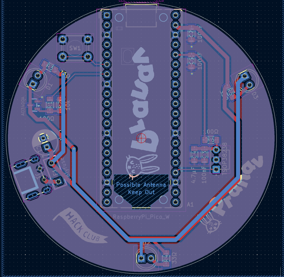
EchoIR is an open-source printed circuit board by bunnypranav, from the bunnypranav/echoIR repository on GitHub. It is a 2-layer board with 23 parts on 41 nets, routed with 65 tracks and 6 vias.
It is built around the AO3400A and TSOP38238. Its parts include 6 resistors, 5 capacitors, 3 diodes, 1 transistor and 1 connector. It belongs with the RP2040 boards of this library.


This is an IR hub, with both an IR receiver and a handful of transmitters, which can control my IR appliances, like the AC, fan, and TV, with my phone and over the internet. It wouldn't replace the remotes, but it could learn their signals and replay them whenever I want from my phone.
Made in KiCad
On the left side is the USB-C connector, going into the polyfuse, then into the +5V rail. The three IR LEDs each have their own 33-ohm resistor and connect from +5V to the IRLEDNODE. When the MOSFET turns on, current flows through all three LEDs to ground. The TSOP38238 receiver runs from +3.3V, which comes from the Pico's internal regulator. There is a 100nF capacitor and a 4.7uF capacitor close to it, because IR receivers are sensitive to noise. The button connected to GPIO 14 controls the "record" mode, with its status led just being the inbuilt Pi led at GPIO25.

Made in KiCad

Written in CircuitPython
The Pico 2W connects to WiFi on boot and starts a HTTP server that exposes a simple webhook endpoint. When I press the button, it enters a short recording window and captures the raw pulse timings from the TSOP38238, then stores them in memory with an incrementing ID number. The IR LEDs are driven from GPIO5 using a 38kHz PWM carrier, and when a POST request is sent to /play with a JSON body like {"id": 3}, the Pico looks up that stored signal and replays it through the three IR transmitters. Everything runs locally on the Pico, so another computer on the same network can trigger appliances just by sending a simple HTTP request. This can also be easily plugged in to home automation services, or be modified to worth with MQTT, something I plan to do in the future.
Designed in Fusion 360
Created a basic CAD base for the PCB to sit on. I did not create any top cover, since the LEDs cannot shine through solid PLA plastic, neither can the TSOP recieve IR pulses. This is just to prevent the bottom pins from scratching the surface I put this on.


| Qty | Value | Footprint | References |
|---|---|---|---|
| 3 | 100nF | Capacitor_SMD:C_1206_3216Metric_Pad1.33x1.80mm_HandSolder | C2, C3, C5 |
| 3 | 33Ω | Resistor_SMD:R_1206_3216Metric_Pad1.30x1.75mm_HandSolder | R3, R4, R5 |
| 3 | LED | LED_THT:LED_D5.0mm | D1, D2, D3 |
| 3 | LOGO | LOGO | G***, G***, G*** |
| 2 | 100Ω | Resistor_SMD:R_1206_3216Metric_Pad1.30x1.75mm_HandSolder | R1, R6 |
| 1 | 10k | Resistor_SMD:R_1206_3216Metric_Pad1.30x1.75mm_HandSolder | R2 |
| 1 | 10µF | Capacitor_THT:CP_Radial_D6.3mm_P2.50mm | C1 |
| 1 | 4.7µF | Capacitor_SMD:C_1206_3216Metric_Pad1.33x1.80mm_HandSolder | C4 |
| 1 | AO3400A | Package_TO_SOT_SMD:SOT-23 | Q1 |
| 1 | Polyfuse | RXEF050:FUS_RXEF050_TYCO_TYC | F1 |
| 1 | RaspberryPi_Pico_W | Module:RaspberryPi_Pico_Common_THT | A1 |
| 1 | SW_Push | Button_Switch_THT:SW_PUSH_6mm | SW1 |
| 1 | TSOP38238 | TSOP38238:XDCR_TSOP38238 | A2 |
| 1 | USB_C_Receptacle_PowerOnly_6P | USBC:USB-C-TH_TYPE-C-31-M-33 | J1 |

haya1010/ir-blaster-kicad
KiCad hardware designs and JLCPCB manufacturing files for the IR blaster project


ajvizganapathy-pixel/FlipperZero-DIY-STM32WB55-NucleusDark
DIY Flipper Zero clone using STM32WB55CGU6 — KiCad PCB, Momentum firmware, 200+ apps, BadUSB scripts, wiring diagrams

CmdrZin/chips_avr_examples
AVR assembly and C code for robotics and other projects.


keener2u/CoinPCB
Simple ESP8266 breakout board shaped like a challenge coin. Built to be a hackable extendable board for IOT projects and given out for recognition and to spark staff's imagination.
23 parts, built around the AO3400A and TSOP38238. The full list of its parts is on this page, with links to each part's symbol and footprint where PCBKit's library has them.
From the bunnypranav/echoIR repository on GitHub, at the commit this page was made from: the board is PCB/echoIR.kicad_pcb and its schematic PCB/echoIR.kicad_sch. PCBKit opens the board in the browser, with nothing to install.
Its repository states no licence, so its author keeps all rights: ask bunnypranav before reusing the design.